Configurators
In this tutorial, you will learn the basics of one of the most powerful features in DynaMaker, i.e. Configurators, including a short guide on how to use your own static assets and textures. In the configurators the parameters play an important role together with the internal rules that make every custom product possible. As a product example, we will use a three-point flexural test in a beam to calculate automatically the bending moment & max deflection for a given cross-section.
For this we will follow 4 steps:
Don't forget to check the common mistakes if you get stuck. Good luck!
1. Prepare Components
For this project we will create 3 components: Beam, Load Tester & Assembly. You can start with a new app with 3 new components, as done in previous tutorials.
A. Beam
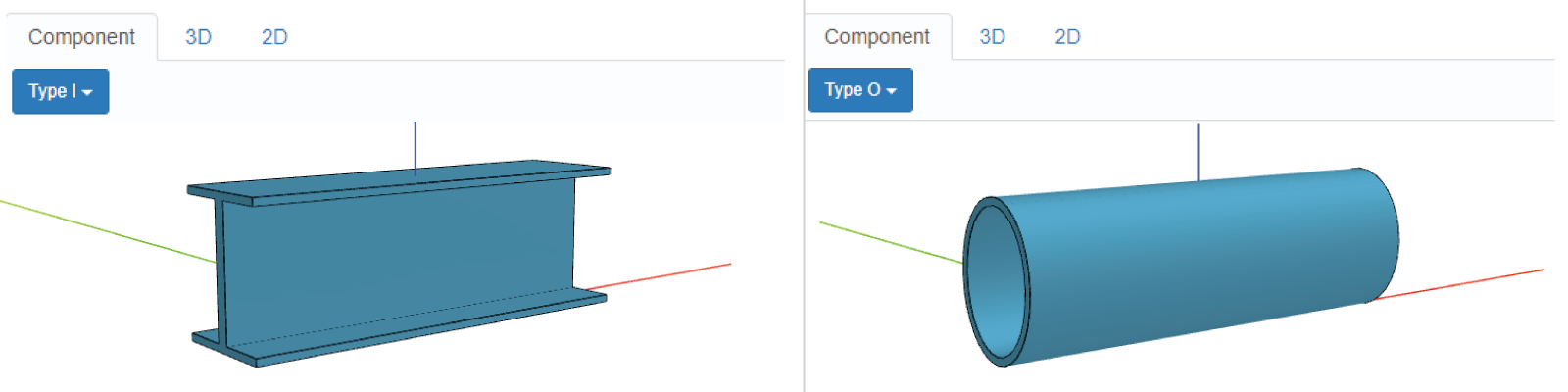
Let's start with the beam. It will contain 2 different profiles: I & O. Apart from being able to modify the main properties (width, depth & height), in the I-profile we should be able to modify the thickness of its web and flanges. For the O-shape, we could make it hollow like a pipe and also modify its thickness.
Making different components for each type of beam (I-beam & O-beam) depends on the complexity of the component and its properties. If they differ too much, then it's preferable to have separate components. However, for simplification and specially when starting a new app, having all properties in the same component is sometimes preferable as we will do here.
This said, let's start with the properties.
Properties
- In CONSTANTS, make sure you have the type of profile as a constant and include the properties types:
export enum PROFILE_TYPE {
  I = 'profile-type-i',
  O = 'profile-type-o',
}

export interface Properties {
  depth: number
  height: number
  width: number
  profileType: PROFILE_TYPE // with this, profileType can only be 'profile-type-o' or 'profile-type-i'

  webThickness: number
  flangeThickness: number

  hollow: boolean
  pipeThickness: number
}
What is enum?
You can think of enum as const but with the type you want. It doesn't need to be strictly either number or
string. In this case PROFILE_TYPE can only be either 'profile-type-i' or 'profile-type-o'. Later on you'll see
why this is more useful than having it as const.
- In API, export the CONSTANTS to be able to use
PROFILE_TYPEin other components. Make sure you have
export * from './component.js'
export * from './constants.js'
You can skip exporting the functions from the tab PARAMETERS (i.e.
export * from './parameters.js'since we will create the configurator from the Assembly). You can also leave this tab empty by removing the test configurator too.
- In COMPONENT, you should have:
export class Component extends STUDIO.BaseComponent<CONSTANTS.Properties> {
  // see that is CONSTANTS.Properties now
  constructor() {
    super()

    this.properties = {
      depth: 50,
      height: 100,
      width: 300,
      profileType: CONSTANTS.PROFILE_TYPE.I,

      // properties for type I:
      webThickness: 10,
      flangeThickness: 5,

      // properties for type O:
      hollow: true,
      pipeThickness: 5,
    }
  }

  generateGeometry() {
    // logic to generate geometry
  }
}
Notice that we moved
interface PropertiestoCONSTANTSto clean the editor tabCOMPONENTand to be able to use later inGEOM3D.
Good, let's create the profile as a sketch for each type of beam.
Profiles
In GEOM2D, you could create the following profile sketches:
export function generateProfileTypeISketch(
  profileWidth: number,
  profileHeight: number,
  webThickness: number,
  flangeThickness: number,
) {
  const sketch = new SKYCAD.Sketch()

  sketch.moveTo(0, 0)
  sketch.lineTo(profileWidth, 0)
  sketch.lineTo(profileWidth, flangeThickness)
  sketch.lineTo((profileWidth + webThickness) / 2, flangeThickness)
  sketch.lineTo((profileWidth + webThickness) / 2, profileHeight - flangeThickness)
  sketch.lineTo(profileWidth, profileHeight - flangeThickness)
  sketch.lineTo(profileWidth, profileHeight)
  sketch.lineTo(0, profileHeight)
  sketch.lineTo(0, profileHeight - flangeThickness)
  sketch.lineTo((profileWidth - webThickness) / 2, profileHeight - flangeThickness)
  sketch.lineTo((profileWidth - webThickness) / 2, flangeThickness)
  sketch.lineTo(0, flangeThickness)
  sketch.lineToId(0) // don't forget to close the sketch to create a closed contour
  sketch.translate(-profileWidth / 2, 0)

  return sketch
}

export function generateProfileTypeOSketch(
  profileWidth: number,
  profileHeight: number,
  hollow: boolean,
  pipeThickness: number,
) {
  const sketch = SKYCAD.generateEllipseSketch(profileWidth / 2, profileHeight / 2)

  if (hollow) {
    const holeSketch = SKYCAD.generateEllipseSketch(profileWidth / 2 - pipeThickness, profileHeight / 2 - pipeThickness)
    sketch.mergeSketch(holeSketch)
  }

  sketch.translate(0, profileHeight / 2)

  return sketch
}
Let's use these sketches to create 3D geometry!
Geometry
We will use all the properties for the geometry and make the profile sketch used for the extrusion dependent on the type. For this:
- In COMPONENT pass all properties to
generateModel()for later.generateGeometry()could look like:
 generateGeometry() {
    const properties = this.getProperties()

    const model = GEOM3D.generateModel(properties)
    const geometryGroup = new SKYCAD.GeometryGroup()
    geometryGroup.addGeometry(model, {
      materials: [new SKYCAD.Material({ color: new SKYCAD.RgbColor(83, 165, 199) })]
    })

    // Optional dimensions to add
    const layout = new SKYCAD.Layout()
    const start = new SKYMATH.Vector2D(0.5 * properties.width, 0)
    const end = new SKYMATH.Vector2D(-0.5 * properties.width, 0)
    layout.addDimension(start, end, { decimals: 0, textSize: 30 })
    geometryGroup.addGeometry(layout)

    return geometryGroup
  }
- In GEOM3D, make sure you choose the right profile for each type:
export function generateModel(properties: CONSTANTS.Properties) {
  const { depth, height, width, profileType, webThickness, flangeThickness, hollow, pipeThickness } = properties
  const model = new SKYCAD.ParametricModel()

  let profileSketch: SKYCAD.Sketch
  switch (profileType) {
    default:
    case CONSTANTS.PROFILE_TYPE.I:
      profileSketch = GEOM2D.generateProfileTypeISketch(depth, height, webThickness, flangeThickness)
      break
    case CONSTANTS.PROFILE_TYPE.O:
      profileSketch = GEOM2D.generateProfileTypeOSketch(depth, height, hollow, pipeThickness)
      break
  }

  const plane = new SKYCAD.Plane(1, 0, 0, -0.5 * width) // perpendicular to x-axis, so the largest beam dimension is parallel to it.
  model.addExtrude(profileSketch, plane, width)

  return model
}
- Save & Update & Publish your Beam component.
- Optionally create presets of each type to easily switch between profiles (review My First Component if you don't remember).
B. Load Tester (static models)
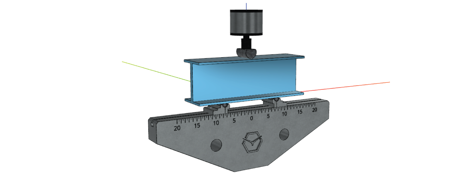
As for the three-point load tester, we will simplify the machine by creating a model that consists of 2 supports or fixtures, one at 1/4 and the other at 3/4 of the beam length, and the load head where the force is applied from. However we know that these parts are always static (because we are configuring the beam and not the machine after all), then we can make use of models that are created in other softwares since they might be already provided by the beam manufacturer perhaps. Now that we are done with the component Beam, let's switch to the second component we created: LoadTester.
Properties
Despite being made of static models, we want to place both fixtures at a dynamic place based on the beam length and
height. Therefore we will have only one property called e.g. beamLength and beamHeight. For that:
- Back in the app dashboard, go into the component LoadTester.
- In COMPONENT, you could have:
interface Properties {
  beamLength: number
  beamHeight: number
}

export class Component extends STUDIO.BaseComponent<Properties> {
  constructor() {
    super()

    this.properties = {
      beamLength: 300,
      beamHeight: 50,
    }
  }

  generateGeometry() {
    // logic for geometry
  }
}
Geometry
As for the geometry, we will use the following static 3D files as GLB (click on the links below to download them):
In order to use these static 3D assets:
- Download them and clean their file name (i.e. rename LOAD_BASE-6548e9b....glb to just LOAD_BASE.glb)
- Go back to the app dashboard.
- Under Files, upload these filesGEOM3D all at once and make sure to click on the checkbox to automatically create static models.
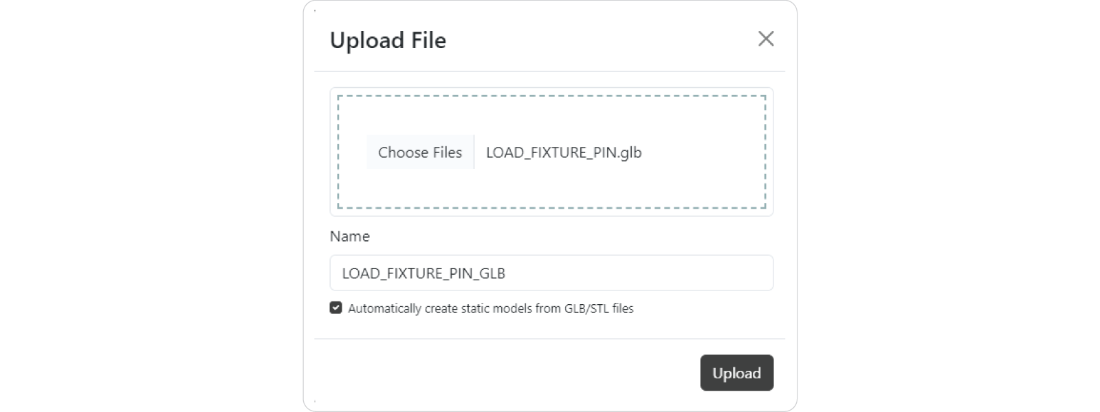
- If you add them one by one, you can customize the name of the file within DynaMaker with the given field:
You could also create the static model manually by clicking on + Create Static Model at the top-right of the Static Models section, giving you the option to upload a reference file (usually a STEP file) that can be used later for exporting the whole geometry in STEP format using the original files. However we will not add source references for this tutorial.
Once you create the static models, you should see them under the Static Models section. If you hover the mouse over
the cube icon next to each static model, you can check their 3D bounds. GLB files are usually
in metres by default, whereas in DynaMaker we usually stick to milimetres for simplicity, so a x1000 scale will be
needed later since the bounds of the model should be in mm (i.e. min: (-250, -30, -150); max: (250, 30, 0)) to be
consistent with the rest of the components. Remember this!

Next let's use this static models in our LoadTester component. For that, we will follow the same methodology as if they are subcomponents of an assembly:
- Go into the component LoadTester.
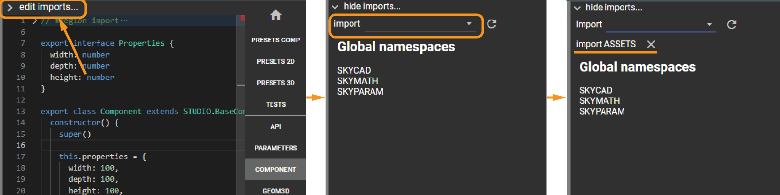
- Open the hidden tab edit imports... at the top of the code section.
- Click on the dropdown import and click on ASSETS.
Now that we have access to the static assets, let's use them! Some notes:
- You can access a static model through the imported ASSETS, like
ASSETS.STATIC_MODELS.LOAD_BASE. See that you can press Ctrl+Space after every.when typing to see all the available options (in this case static models). If you don't see them or miss someone recently uploaded, you must refresh the page (F5) to get the latest data. - In
generateGeometry()add the base and cell directly to thegeometryGroup, considering the latter with a position dependent onbeamHeight. - Create a second geometry group (e.g.
fixtureGeometry) dedicated only for the fixture (i.e. with the fixture base and pin), since we will add one and duplicate it. - Include the bolt and nut in said
fixtureGeometryso it gets duplicated too. - Add this
fixtureGeometrytwice togeometryGroupwith a position dependent on the propertybeamLength. - The fixture height is
28mm, so make sure their highest point is aligned with the bottom face of the beam, i.e. the x-axis. - Remember to scale all static models (i.e.
scale: 1000) when adding them togeometryGroup.
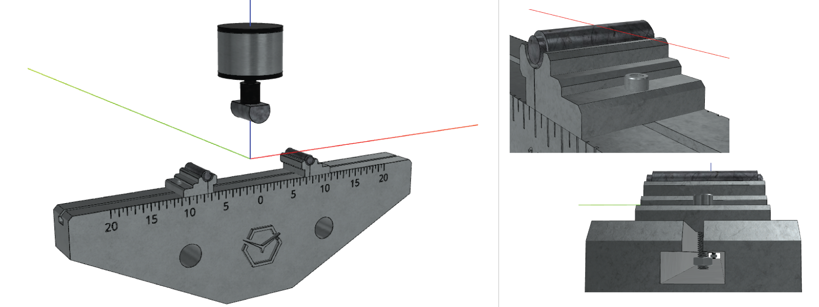
Considering these points, you should end up having something like the following with its code below.
generateGeometry() {
  const { beamHeight, beamLength } = this.getProperties()
  const geometryGroup = new SKYCAD.GeometryGroup()

  const FIXTURE_HEIGHT = 28

  geometryGroup.addGeometry(ASSETS.STATIC_MODELS.LOAD_BASE, {
    position: new SKYMATH.Vector3D(0, 0, -FIXTURE_HEIGHT),
    scale: 1000,
  })

  geometryGroup.addGeometry(ASSETS.STATIC_MODELS.LOAD_CELL, {
    position: new SKYMATH.Vector3D(0, 0, beamHeight),
    scale: 1000,
  })

  const fixtureGeometry = new SKYCAD.GeometryGroup()

  fixtureGeometry.addGeometry(ASSETS.STATIC_MODELS.LOAD_FIXTURE_BASE)
  fixtureGeometry.addGeometry(ASSETS.STATIC_MODELS.LOAD_FIXTURE_PIN)
  fixtureGeometry.addGeometry(ASSETS.STATIC_MODELS.BOLT, {
    position: new SKYMATH.Vector3D(0.026, 0, 0.01),
  })
  fixtureGeometry.addGeometry(ASSETS.STATIC_MODELS.NUT, {
    position: new SKYMATH.Vector3D(0.026, 0, 0.01),
  })

  console.log(fixtureGeometry.getBounds().max.z * 1000)

  geometryGroup.addGeometry(fixtureGeometry, {
    position: new SKYMATH.Vector3D(-0.25 * beamLength, 0, -FIXTURE_HEIGHT),
    rotation: new SKYMATH.Vector3D(0, 0, Math.PI),
    scale: 1000,
  })
  geometryGroup.addGeometry(fixtureGeometry, {
    position: new SKYMATH.Vector3D(0.25 * beamLength, 0, -FIXTURE_HEIGHT),
    scale: 1000,
  })

  return geometryGroup
}
See that the position of some static models must be adjusted when adding them to the geometry with some constants (like
FIXTURE_HEIGHT). This could have been avoided if the static assets are corrected from the begninning (i.e. adjusted from the software that export the geometry as GLB in this case) so that "magic" placement in DynaMaker can be avoided afterwards. Then if you have access to the original files, make sure to position them according to their use in the DynaMaker app.
- Save & Update & Publish your Load Tester component.
C. Assembly
The Assembly component will just consist of both components Beam & LoadTester. It will also include the main configurator that will be used in the application, meaning its parameters will update the properties of the subcomponents.
Import Subcomponents
Make sure to import the components Beam & LoadTester into the Assembly component via edit imports...
Properties
The properties of the Assembly will be the same as the Beam. In COMPONENT have the following, including
instances of the Beam and LoadTester within the constructor since we will always have one beam and one load
tester:
export class Component extends STUDIO.BaseComponent<BEAM.Properties> {
  constructor() {
    super()

    this.properties = {
      depth: 50,
      height: 100,
      width: 300,
      profileType: BEAM.PROFILE_TYPE.I,

      // properties for type I
      webThickness: 10,
      flangeThickness: 5,

      // properties for type O
      hollow: true,
      pipeThickness: 5,
    }

    const beamComponent = new BEAM.Component()
    this.componentHandler.add(beamComponent)

    const loadTesterComponent = new LOADTESTER.Component()
    this.componentHandler.add(loadTesterComponent)

    this.update() // function that will update the subcomponents
  }

  update() {
    // logic to be added soon
  }

  generateGeometry() {
    // logic for geometry
  }
}
Notice that the type of the Assembly properties are the same as the Beam properties. Although we did this for simplicity of the tutorial, this is very dangerous to do if we ever want to decouple the properties between components (e.g. beam should have 1 more property that the assembly shouldn't have).
Remember that in order to be able to use
PROFILE_TYPEfrom the Beam component, CONSTANTS has to be exported via its API. Make sure to haveexport \* from './constants.js'in the Beam as shown previously.
Subcomponents
In update() get the subcomponens directly from the componentHandler (since we added them in the constructor), and
set the properties accordingly:
update() {
  const { depth, height, width, profileType, webThickness, flangeThickness, hollow, pipeThickness } = this.getProperties()

  const beamComponent = this.componentHandler.getComponents(BEAM.Component)[0]!
  beamComponent.setProperties({ depth, height, width, profileType, webThickness, flangeThickness, hollow, pipeThickness })

  const loadTesterComponent = this.componentHandler.getComponents(LOADTESTER.Component)[0]!
  loadTesterComponent.setProperties({ beamHeight: height, beamLength: width })
}
See that we can retrieve the component directly from the list that gives the
componenthHandleras the first item of said components. In this assembly we always have 1 beam and 1 load tester, which is usually not the case for other products. You usually would need to add if-statements to make sure you have at least one component to avoid undesired bugs.
Geometry
Simply add the subcomponents geometry in the Assembly in the same way you did in previous tutorials:
generateGeometry() {
  return this.componentHandler.generateAllGeometry()
}
If you published Beam & LoadTester correctly, you should see them when Save & Update.
2. Parameters
When designing a configurator, the workflow for the parameters must be consistent and sometimes identifying the top-level parameters could be a challenge to make a user-friendly app.
In this case, we have 8 properties and we can easily make a parameter for each through the
library SKYPARAM. Let's add all of them for now. In the Assembly component, go to
PARAMETERS and create slider, input or dropdown parameters accordingly.
The configurator with these parameters could look like:
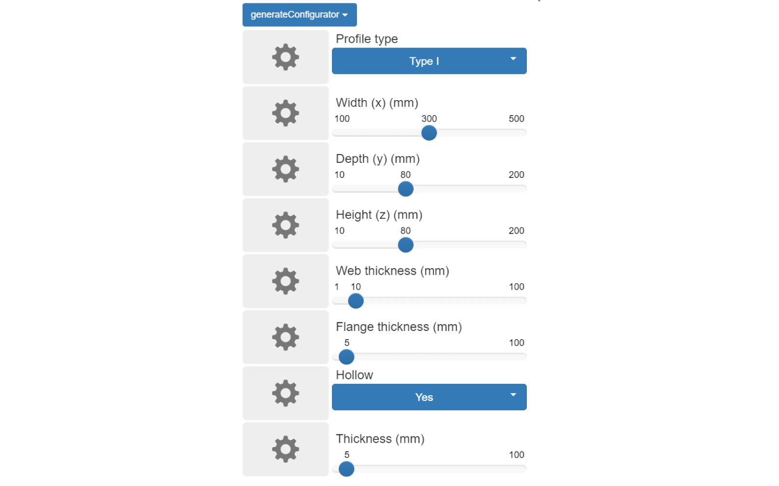
Try yourself first and compare your result with this generateConfigurator():
const PARAMETER = {
  PROFILE_TYPE: 'profile-type-parameter',
  WIDTH: 'width-parameter',
  DEPTH: 'depth-parameter',
  HEIGHT: 'height-parameter',
  WEB_THICKNESS: 'web-thickness-parameter',
  FLANGE_THICKNESS: 'flange-thickness-parameter',
  HOLLOW: 'hollow-parameter',
  PIPE_THICKNESS: 'pipe-thickness-parameter',
}

export function generateConfigurator(component: COMPONENT.Component): SKYPARAM.Configurator {
  const { profileType, width, depth, height, webThickness, flangeThickness, hollow, pipeThickness } =
    component.getProperties()

  const profileTypeParameter = SKYPARAM.generateDropdown(PARAMETER.PROFILE_TYPE, 'Profile type', [
    new SKYPARAM.DropdownItem('Type I', BEAM.PROFILE_TYPE.I),
    new SKYPARAM.DropdownItem('Type O', BEAM.PROFILE_TYPE.O),
  ])
  profileTypeParameter.setValue(profileType)

  const widthParameter = SKYPARAM.generateSlider(PARAMETER.WIDTH, 'Width (x)', {
    defaultValue: width,
    maxValue: 800,
    minValue: 100,
    stepSize: 1,
    unit: 'mm',
  })

  const depthParameter = SKYPARAM.generateSlider(PARAMETER.DEPTH, 'Depth (y)', {
    defaultValue: depth,
    maxValue: 200,
    minValue: 10,
    stepSize: 1,
    unit: 'mm',
  })

  const heightParameter = SKYPARAM.generateSlider(PARAMETER.HEIGHT, 'Height (z)', {
    defaultValue: height,
    maxValue: 200,
    minValue: 10,
    stepSize: 1,
    unit: 'mm',
  })

  const webThicknessParameter = SKYPARAM.generateSlider(PARAMETER.WEB_THICKNESS, 'Web thickness', {
    defaultValue: webThickness,
    maxValue: 100,
    minValue: 1,
    stepSize: 1,
    unit: 'mm',
  })

  const flangeThicknessParameter = SKYPARAM.generateSlider(PARAMETER.FLANGE_THICKNESS, 'Flange thickness', {
    defaultValue: flangeThickness,
    maxValue: 100,
    minValue: 1,
    stepSize: 0.5,
    unit: 'mm',
  })

  const hollowParameter = SKYPARAM.generateDropdown(PARAMETER.HOLLOW, 'Hollow', [
    new SKYPARAM.DropdownItem('Yes', true),
    new SKYPARAM.DropdownItem('No', false),
  ])
  hollowParameter.setValue(hollow)

  const pipeThicknessParameter = SKYPARAM.generateSlider(PARAMETER.PIPE_THICKNESS, 'Thickness', {
    defaultValue: pipeThickness,
    maxValue: 100,
    minValue: 1,
    stepSize: 1,
    unit: 'mm',
  })

  const configurableParameters = [
    profileTypeParameter,
    widthParameter,
    depthParameter,
    heightParameter,
    webThicknessParameter,
    flangeThicknessParameter,
    hollowParameter,
    pipeThicknessParameter,
  ]

  const configurator = new SKYPARAM.Configurator(configurableParameters)

  // configurator callback to add

  return configurator
}
Great! Now we need to update the properties according to the values of the parameters. This is usually done in the
completion callback:
// PARAMETER keys

export function generateConfigurator(component: COMPONENT.Component): SKYPARAM.Configurator {
  // configurableParameters

  const configurator = new SKYPARAM.Configurator(configurableParameters)

  configurator.addCompletionCallback((valid, values) => {
    if (valid) {
      component.setProperties({
        depth: values[PARAMETER.DEPTH],
        height: values[PARAMETER.HEIGHT],
        width: values[PARAMETER.WIDTH],
        profileType: values[PARAMETER.PROFILE_TYPE],
        webThickness: values[PARAMETER.WEB_THICKNESS],
        flangeThickness: values[PARAMETER.FLANGE_THICKNESS],
        hollow: values[PARAMETER.HOLLOW],
        pipeThickness: values[PARAMETER.PIPE_THICKNESS],
      })
    }
  })

  return configurator
}
Notice that
addCompletionCallbackgives two arguments to use:
valid: as a boolean,truewhen all parameters are valid (e.g. within the max-min range)values: as an object with the keys of all parameters, containing their values from the configurator.
You can try different values for the parameters and check that they are all correctly connected. However, you will
immediately realize that sometimes some parameters are not needed (e.g. Hollow for a Type I profile) or their
max-min range makes self-colliding shapes. This can be easily fixed with rules!
3. Rules
To set up a rule in a configurator you need to add a setUpdateRule() for each parameter you want a rule for. Let's
start with the simplest: hiding those that are not needed depending on the profile, like:
export function generateConfigurator(component: COMPONENT.Component): SKYPARAM.Configurator {
  // configurableParameters

  const configurator = new SKYPARAM.Configurator(configurableParameters)

  configurator.setUpdateRule(PARAMETER.WEB_THICKNESS, (value, directUpdate, parameter, values) => {
    if (!directUpdate) {
      const newProfileType = values[PARAMETER.PROFILE_TYPE]
      switch (newProfileType) {
        case BEAM.PROFILE_TYPE.I:
          parameter.setVisible(true)
          break
        case BEAM.PROFILE_TYPE.O:
          parameter.setVisible(false)
          break
      }
    }
  })
  configurator.setUpdateRule(PARAMETER.FLANGE_THICKNESS, (value, directUpdate, parameter, values) => {
    if (!directUpdate) {
      const newProfileType = values[PARAMETER.PROFILE_TYPE]
      switch (newProfileType) {
        case BEAM.PROFILE_TYPE.I:
          parameter.setVisible(true)
          break
        case BEAM.PROFILE_TYPE.O:
          parameter.setVisible(false)
          break
      }
    }
  })
  configurator.setUpdateRule(PARAMETER.HOLLOW, (value, directUpdate, parameter, values) => {
    if (!directUpdate) {
      const newProfileType = values[PARAMETER.PROFILE_TYPE]
      switch (newProfileType) {
        case BEAM.PROFILE_TYPE.I:
          parameter.setVisible(false)
          break
        case BEAM.PROFILE_TYPE.O:
          parameter.setVisible(true)
          break
      }
    }
  })
  configurator.setUpdateRule(PARAMETER.PIPE_THICKNESS, (value, directUpdate, parameter, values) => {
    if (!directUpdate) {
      const newProfileType = values[PARAMETER.PROFILE_TYPE]
      switch (newProfileType) {
        case BEAM.PROFILE_TYPE.I:
          parameter.setVisible(false)
          break
        case BEAM.PROFILE_TYPE.O:
          parameter.setVisible(values[PARAMETER.HOLLOW])
          break
      }
    }
  })

  // configurator callback

  return configurator
}
See that the callback needed in
setUpdateRule()gives 4 arguments:
value: as the current value of the parameter.directUpdate: as a boolean,truewhen the parameter is being updated (e.g. changing the value for slider or option for dropdown). Usually, you want to trigger the rule when something else is updated (so thatdirectUpdate = false).parameter: as the parameter with all its SKYPARAM properties (e.g. visibility, max/min values, etc).values: as an object with the keys of all parameters above this parameter, so that the rules are always triggered downstream according to their order within the configurator.Also, you need to remember that visibility doesn't mean that you remove the parameter, you simply hide it. That means that you will get its value if you try to read it, it will update the property connected to it accordingly and even make the configurator invalid if you forgot to update its value properly.
As for the sliders, you noticed that we need to update the max & min values for the thickness parameters for both
profiles. For example, it makes no sense to have a web wider than the actual profile width and so on. Let's add some
rules for those! For that we will use the argument parameter that the callback of configurator.setUpdateRule() gives
us to use, and we can easily set max and min values through parameter.setMax() and parameter.setMin().
Try yourself first and compare your result with this updated generateConfigurator():
const PARAMETER = {
  PROFILE_TYPE: 'profile-type-parameter',
  WIDTH: 'width-parameter',
  DEPTH: 'depth-parameter',
  HEIGHT: 'height-parameter',
  WEB_THICKNESS: 'web-thickness-parameter',
  FLANGE_THICKNESS: 'flange-thickness-parameter',
  HOLLOW: 'hollow-parameter',
  PIPE_THICKNESS: 'pipe-thickness-parameter',
}

export function generateConfigurator(component: COMPONENT.Component): SKYPARAM.Configurator {
  const { profileType, width, depth, height, webThickness, flangeThickness, hollow, pipeThickness } =
    component.getProperties()

  const profileTypeParameter = SKYPARAM.generateDropdown(PARAMETER.PROFILE_TYPE, 'Profile type', [
    new SKYPARAM.DropdownItem('Type I', BEAM.PROFILE_TYPE.I),
    new SKYPARAM.DropdownItem('Type O', BEAM.PROFILE_TYPE.O),
  ])
  profileTypeParameter.setValue(profileType)

  const widthParameter = SKYPARAM.generateSlider(PARAMETER.WIDTH, 'Width (x)', {
    defaultValue: width,
    maxValue: 500,
    minValue: 100,
    stepSize: 1,
    unit: 'mm',
  })

  const depthParameter = SKYPARAM.generateSlider(PARAMETER.DEPTH, 'Depth (y)', {
    defaultValue: depth,
    maxValue: 200,
    minValue: 10,
    stepSize: 1,
    unit: 'mm',
  })

  const heightParameter = SKYPARAM.generateSlider(PARAMETER.HEIGHT, 'Height (z)', {
    defaultValue: height,
    maxValue: 200,
    minValue: 10,
    stepSize: 1,
    unit: 'mm',
  })

  const webThicknessParameter = SKYPARAM.generateSlider(PARAMETER.WEB_THICKNESS, 'Web thickness', {
    defaultValue: webThickness,
    maxValue: 100,
    minValue: 1,
    stepSize: 1,
    unit: 'mm',
  })

  const flangeThicknessParameter = SKYPARAM.generateSlider(PARAMETER.FLANGE_THICKNESS, 'Flange thickness', {
    defaultValue: flangeThickness,
    maxValue: 100,
    minValue: 1,
    stepSize: 0.5,
    unit: 'mm',
  })

  const hollowParameter = SKYPARAM.generateDropdown(PARAMETER.HOLLOW, 'Hollow', [
    new SKYPARAM.DropdownItem('Yes', true),
    new SKYPARAM.DropdownItem('No', false),
  ])
  hollowParameter.setValue(hollow)

  const pipeThicknessParameter = SKYPARAM.generateSlider(PARAMETER.PIPE_THICKNESS, 'Thickness', {
    defaultValue: pipeThickness,
    maxValue: 100,
    minValue: 1,
    stepSize: 1,
    unit: 'mm',
  })

  const configurableParameters = [
    profileTypeParameter,
    widthParameter,
    depthParameter,
    heightParameter,
    webThicknessParameter,
    flangeThicknessParameter,
    hollowParameter,
    pipeThicknessParameter,
  ]

  const configurator = new SKYPARAM.Configurator(configurableParameters)

  configurator.setUpdateRule(PARAMETER.WEB_THICKNESS, (value, directUpdate, parameter, values) => {
    if (!directUpdate) {
      const newProfileType = values[PARAMETER.PROFILE_TYPE]

      // visibility rule
      switch (newProfileType) {
        case BEAM.PROFILE_TYPE.I:
          parameter.setVisible(true)
          break
        case BEAM.PROFILE_TYPE.O:
          parameter.setVisible(false)
          break
      }

      // max rule
      if (parameter.getVisible() === true) {
        const maxValue = values[PARAMETER.DEPTH]
        parameter.setMax(maxValue)
        if (value > maxValue) parameter.setValue(maxValue)
      }
    }
  })

  configurator.setUpdateRule(PARAMETER.FLANGE_THICKNESS, (value, directUpdate, parameter, values) => {
    if (!directUpdate) {
      const newProfileType = values[PARAMETER.PROFILE_TYPE]

      // visibillity rule
      switch (newProfileType) {
        case BEAM.PROFILE_TYPE.I:
          parameter.setVisible(true)
          break
        case BEAM.PROFILE_TYPE.O:
          parameter.setVisible(false)
          break
      }

      // max rule
      if (parameter.getVisible() === true) {
        const maxValue = values[PARAMETER.HEIGHT] / 2 - 1
        parameter.setMax(maxValue)
        if (value > maxValue) parameter.setValue(maxValue)
      }
    }
  })

  configurator.setUpdateRule(PARAMETER.HOLLOW, (value, directUpdate, parameter, values) => {
    if (!directUpdate) {
      const newProfileType = values[PARAMETER.PROFILE_TYPE]

      // visibility rule
      switch (newProfileType) {
        case BEAM.PROFILE_TYPE.I:
          parameter.setVisible(false)
          break
        case BEAM.PROFILE_TYPE.O:
          parameter.setVisible(true)
          break
      }
    }
  })

  configurator.setUpdateRule(PARAMETER.PIPE_THICKNESS, (value, directUpdate, parameter, values) => {
    if (!directUpdate) {
      const newProfileType = values[PARAMETER.PROFILE_TYPE]

      // visibility rule
      switch (newProfileType) {
        case BEAM.PROFILE_TYPE.I:
          parameter.setVisible(false)
          break
        case BEAM.PROFILE_TYPE.O:
          parameter.setVisible(values[PARAMETER.HOLLOW])
          break
      }

      // max rule
      if (parameter.getVisible() === true) {
        const maxValue = Math.min(values[PARAMETER.DEPTH], values[PARAMETER.HEIGHT]) / 2 - 1
        parameter.setMax(maxValue)
        if (value > maxValue) parameter.setValue(maxValue)
      }
    }
  })

  configurator.addCompletionCallback((valid, values) => {
    if (valid) {
      component.setProperties({
        depth: values[PARAMETER.DEPTH],
        height: values[PARAMETER.HEIGHT],
        width: values[PARAMETER.WIDTH],
        profileType: values[PARAMETER.PROFILE_TYPE],
        webThickness: values[PARAMETER.WEB_THICKNESS],
        flangeThickness: values[PARAMETER.FLANGE_THICKNESS],
        hollow: values[PARAMETER.HOLLOW],
        pipeThickness: values[PARAMETER.PIPE_THICKNESS],
      })
    }
  })

  return configurator
}
See that the max value is only updated if the parameter is visible. This could be sometimes ambiguous and to make it clearer the right profile type could be checked instead of the visibility.
Also to avoid bugs, you shouldn't update the properties (in
addCompletionCallback()) with parameters that don't exist (or are hidden) in the configurator, but for now we can leave it like this.
A very common mistake is to mix properties with parameter values. In a rule, having newProfileType as the value that
comes from the parameter could help you understand that this is not the property, which should come from
component.getProperties() instead.
There is an extensive guide with detailed examples of how rules can affect other configurators in the library SKYPARAM.
4. Materials
Materials in DynaMaker can change drastically the appearance of your components. Apart from color and metalness as
we have been seeing so far, it's good to have a good understanding of the rest of the properties that you can change in
a material, specially those related to textures and what the possibilities are around your models. For this, we will see
how they can affect:
A. Parametric Models
All the models you create parametrically in DynaMaker, i.e. extrusions/cuts given a sketch, are
SKYCAD.ParametricModel. As the name implies, these models can be parametric, meaning that they can be bound to a
property or variable, which gives almost-infinite different variantions of a geometry. The beam model is a perfect
example of a SKYCAD.ParametricModel, where we can change pretty much anything of the geometry through properties.
Therefore a DynaMaker material (SKYCAD.Material) can be applied to these models without any restriction. As an
example, we will:
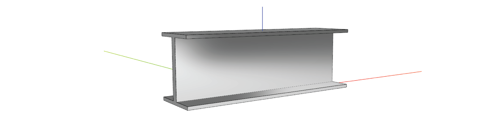
- a) change the color of the beam to grey and give a metallic feeling
- b) leave its ends a bit darker as a result of cutting them poorly in the extrusion manufacturing process for example.
- c) add a texture
We will focus on the component Beam and the mdoel materials in generateGeometry().
a) change color and metalness
const materials = [
  new SKYCAD.Material({
    color: new SKYCAD.RgbColor(200, 200, 200),
    metalness: 1,
    roughness: 0,
  }),
]
geometryGroup.addGeometry(model, { materials })
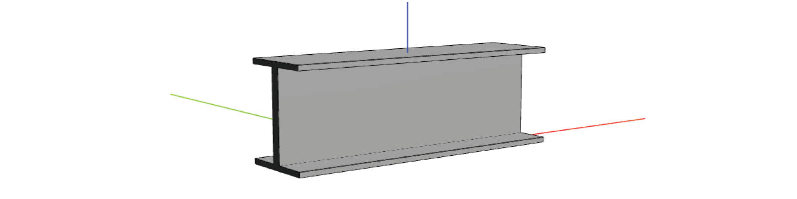
b) change color of just ends
surfaceGroup requires a SKYCAD.SURFACE_GROUP whose definition depends on how the model was performed. This is best
for models that are created with one feature (e.g. extrusion). Alternatively, surfaceIndexList with a list of the
faces as IDs (e.g. surfaceIndexList: [0, 1, 3]) applies the material to those specific faces. However the faces IDs
are assigned randomly and is best to use when having simple geometries.
const materials = [
  new SKYCAD.Material({
    color: new SKYCAD.RgbColor(40, 40, 40),
    surfaceGroup: SKYCAD.SURFACE_GROUP.BASE,
  }),
  new SKYCAD.Material({
    color: new SKYCAD.RgbColor(200, 200, 200),
    surfaceGroup: SKYCAD.SURFACE_GROUP.SIDE,
  }),
  new SKYCAD.Material({
    color: new SKYCAD.RgbColor(100, 100, 100),
    surfaceGroup: SKYCAD.SURFACE_GROUP.TOP,
  }),
]
geometryGroup.addGeometry(model, { materials })
c) add texture
A texture is considered a picture that can be repeated endlessly without noticing the seam between pictures, i.e. a tiled-picture. It usually comes with more "properties" as pictures like metalness, roughness and displacement, but we will focus on just two:
- color picture: that gives the color and possible patterns (e.g. veins in marble).
- normal picture: that creates a feeling of 3D affecting how the lighting "reacts" to the model surfaces.
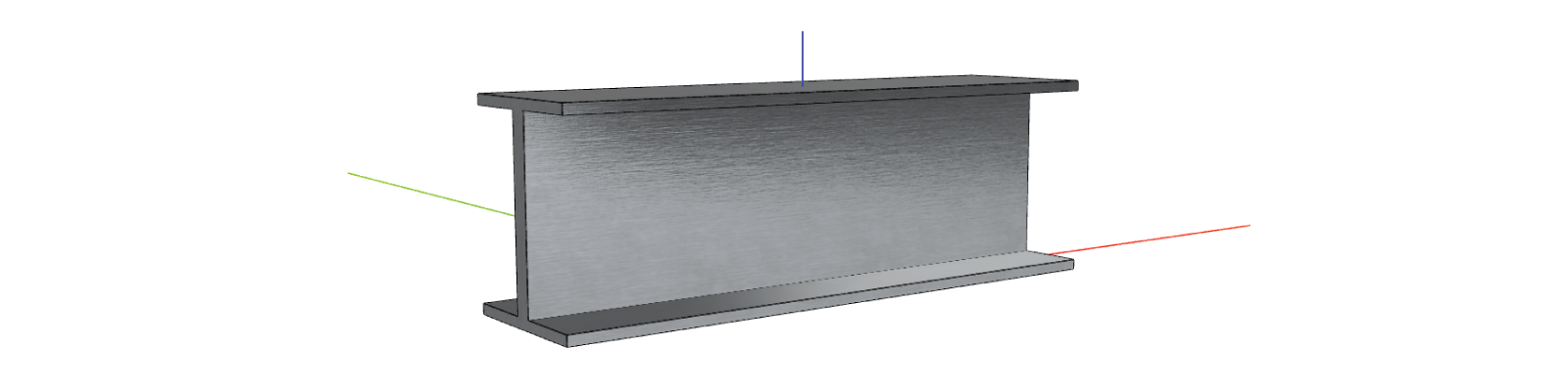
For this example, we will add a brushed metal texture to the beam using these files:
In order to create a texture:
- upload thse two files to Files of the app dashboard.
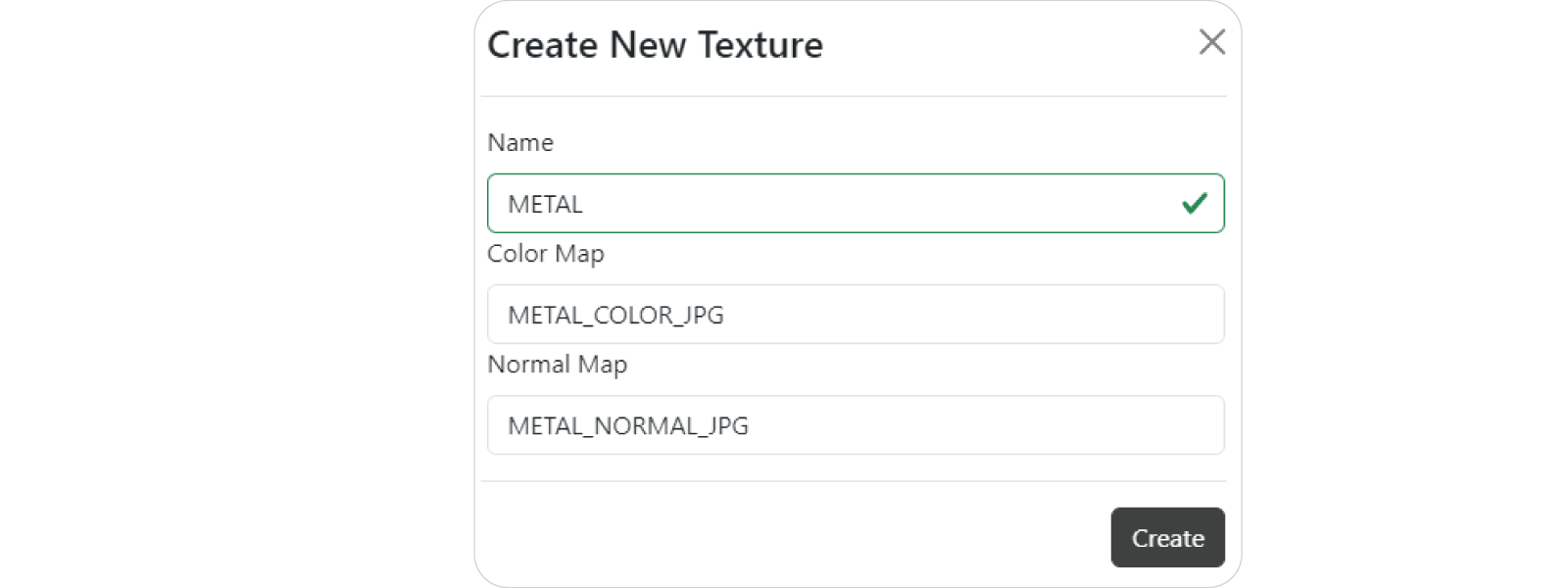
- click on + Create Texture to the right of the Textures section.
- name it
METALadd these pictures to the corresponding fields:
In order to use this texture:
- go back into the component Beam.
- import ASSETS at the top of the code editor.
- use the arguments
textureId,textureRotationandtextureHeightto adjust the texture to your liking in size and direction. - don't forget to adjust the metalness since it doesn't come with the texture.
const materials = [
  new SKYCAD.Material({
    textureId: ASSETS.TEXTURES.METAL,
    textureRotation: Math.PI / 2,
    textureHeight: 100,
    metalness: 1,
    roughness: 0,
  }),
]
geometryGroup.addGeometry(model, { materials })
B. Static Models
In constrast with parametric models, static ones are by definition static and cannot change. However the only property
that you can change in a material applied to a static model is color and metalness. Static models usually have
complex geometries and is best that these come with textures built in the model (i.e. GLB format) as it has been done
with the load tester. The advantage of using GLB files is that they come with different materials and therefore one can
overwrite the color of one of the materials of the static model. As example we intentionally prepared the GLB file for
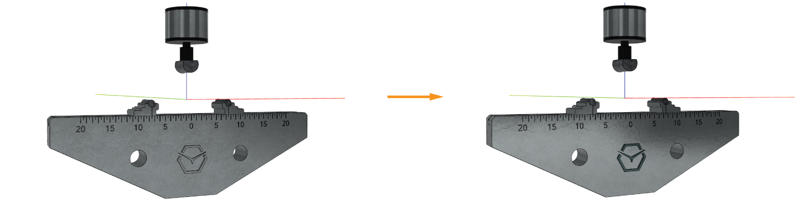
the base of the load tester for this example: we will change the color of the SkyMaker logo built in the GLB file. For
this:
- go back into the component LoadTester.
- even though some GLB files might have the metalness built-in its textures (as done in this case), add the
metallicMaterialsfrom below to every model, to increase the shine of the model for a better light constrast.const metallicMaterials = [new SKYCAD.Material({ metalness: 1, roughness: 0 })] - for changing the color of just the logo we will override the materials with names Logo material and Metal material
that comes with the GLB file as:
const baseMaterials = [
  new SKYCAD.Material({
    overrideCritera: (properties) => {
      return properties.name.includes('Metal material')
    },
    metalness: 1,
    roughness: 0,
  }),
  new SKYCAD.Material({
    overrideCritera: (properties) => {
      return properties.name.includes('Logo material')
    },
    color: 0x759597,
    metalness: 1,
    roughness: 0,
  }),
]
geometryGroup.addGeometry(ASSETS.STATIC_MODELS.LOAD_BASE, {
  materials: baseMaterials,
  position: new SKYMATH.Vector3D(0, 0, -FIXTURE_HEIGHT),
  scale: 1000,
})
Keep in mind that static models cannot change by definition, but that doesn't mean that you cannot replace them for other different static models. Let's say that the fixtures can change in size depending on the beam depth. Therefore if there are 3 types of fixtures (e.g. small, medium and large size), it's a matter of showing the correct static model based on a property called e.g.
fixtureTypeas we have done with the beamprofileType.
Congratulations! You have learned the basics of how to work with configurators, static models and materials. If we put this into an app it could look something like this:
Now that you know the basics of components, drawings & configurators, it's time to go through the user interface of the application that uses all this and for that, we will go through the UI Editor in the next tutorial User Interface.