Introduction to DynaMaker
Get started with DynaMaker by creating a simple cube. After you create your account at app.dynamaker.com, you will learn the basics in three short steps:
- Create app.
- Create a component block.
- Understand Component Editor by extruding the 2D sketch.
Across these tutorials functionality is introduced gradually so you learn not just how things work but why. Explore the docs at any time, but avoid skipping tutorials so concepts build in order.
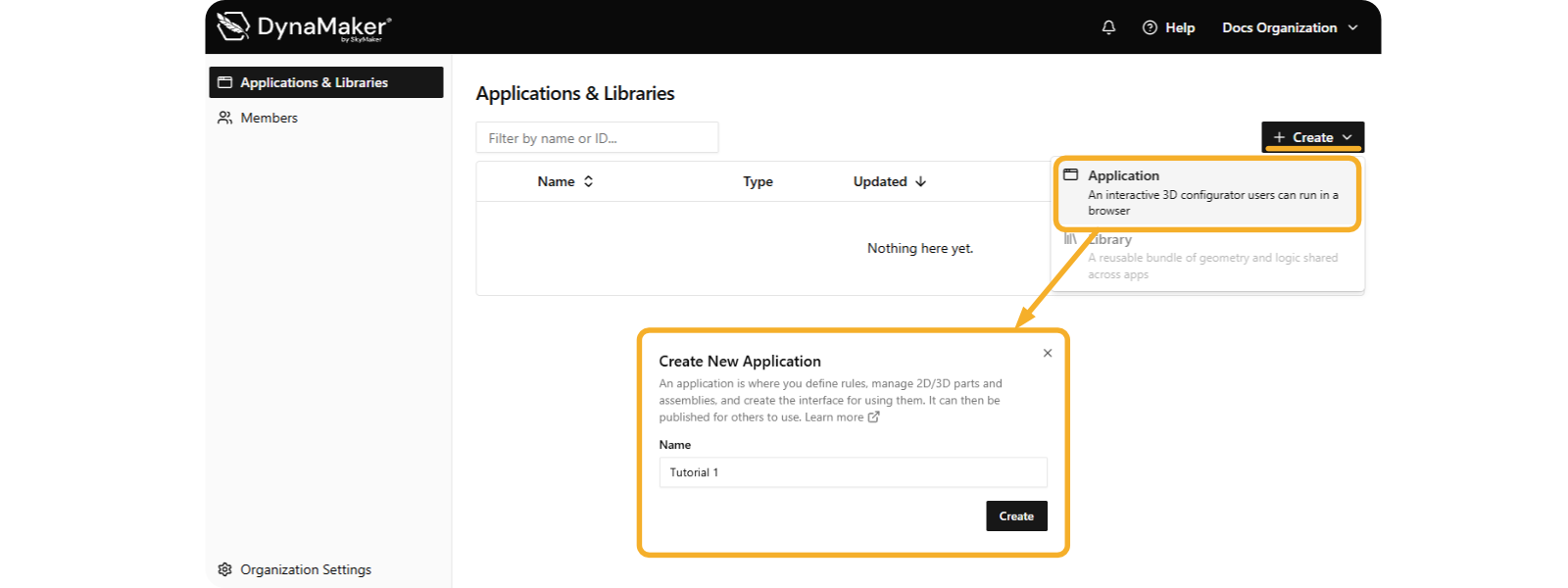
1. Create App
Start by creating your first app and name it Tutorial 1:
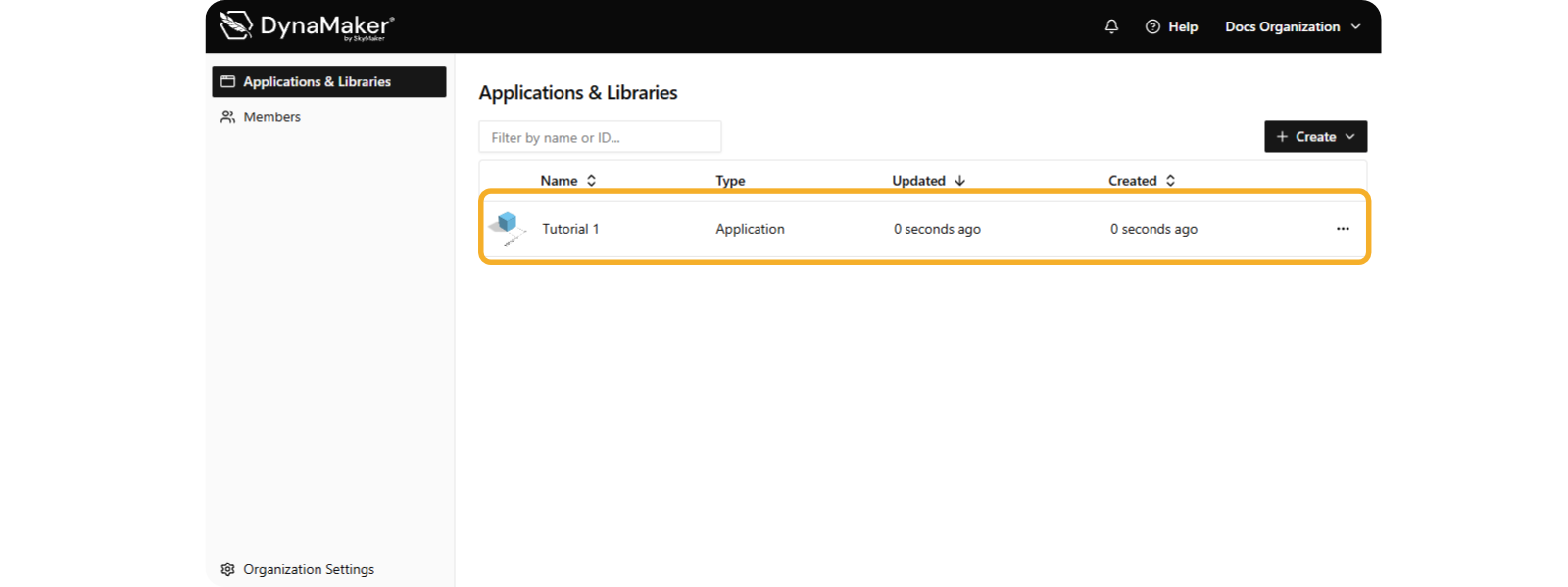
You now see your new app under Applications & Libraries:
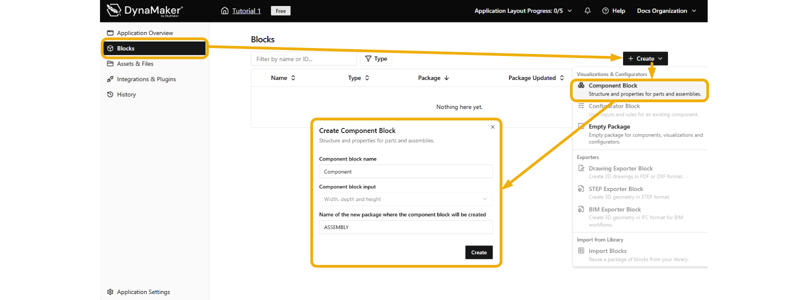
2. Create Component Block
Go into the app, and create yor first Component Block:
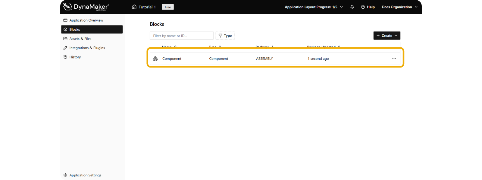
You now see your new block under Blocks:
3. Understand Component Editor
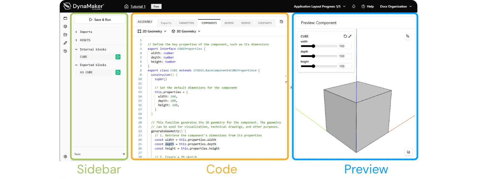
When you step into this new component block you will see the Component Editor consisting of:
- Code (middle) contains the new component and its function that creates the cube.
- Preview (right) shows the generated cube with its name and dynamic sliders for size.
- Sidebar (left) lists functions in this editor. The visualized one has its ▶️-icon green.
In the default template with the cube, you will find that generateGeometry() is in charge of generating the model as
an extrusion (i.e. model.addExtrude(sketch, plane, extrusionLength)) consisting of 3 inputs:
sketchas the base shape of the extrusion, in this case a rectangle with sizewidthanddepth.planeas the direction of the extrusion, in this case the ground plane by default.extrusionLengthas the extrusion length, in this case theheight.
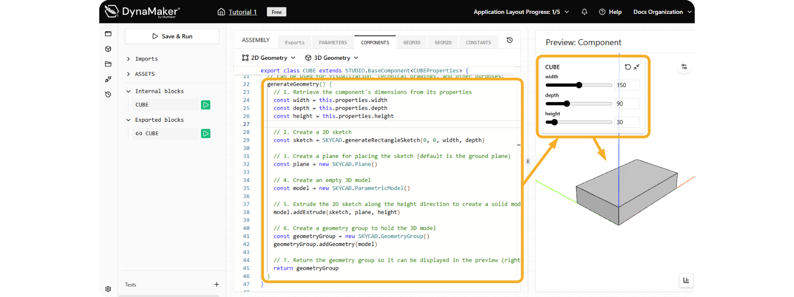
Since the geometry is already connected to the properties of the component, you will see the panel with sliders at the top of the preview section, where you can test and see the model update dynamically.
You have learned the basics of the component editor. The next tutorial (Extrusions & Cuts) dives into code and starts modifying the model.