Drawings
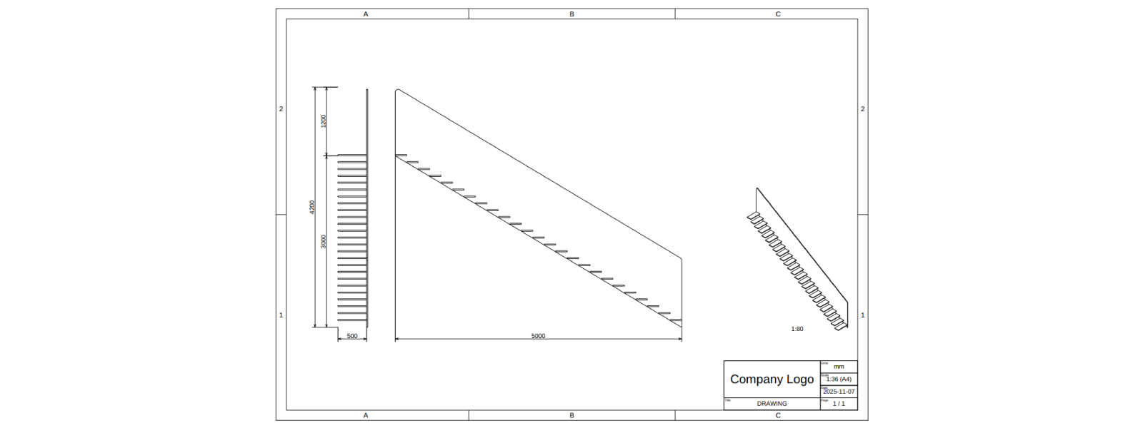
In this tutorial, you will learn how to create and autogenerate 2D drawings. As a product example, we will reuse the staircase from Assemblies and aim for something like the following:
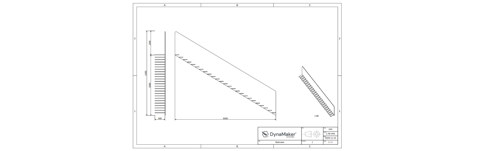
For this we will follow 5 steps:
1. Drawing Exporter
A. Copy app
In the dashboard, you can clone or copy an entire app via •••:
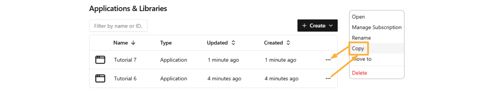
It's very recommended to do a copy of an app or component, as backup, especially when introducing breaking changes.
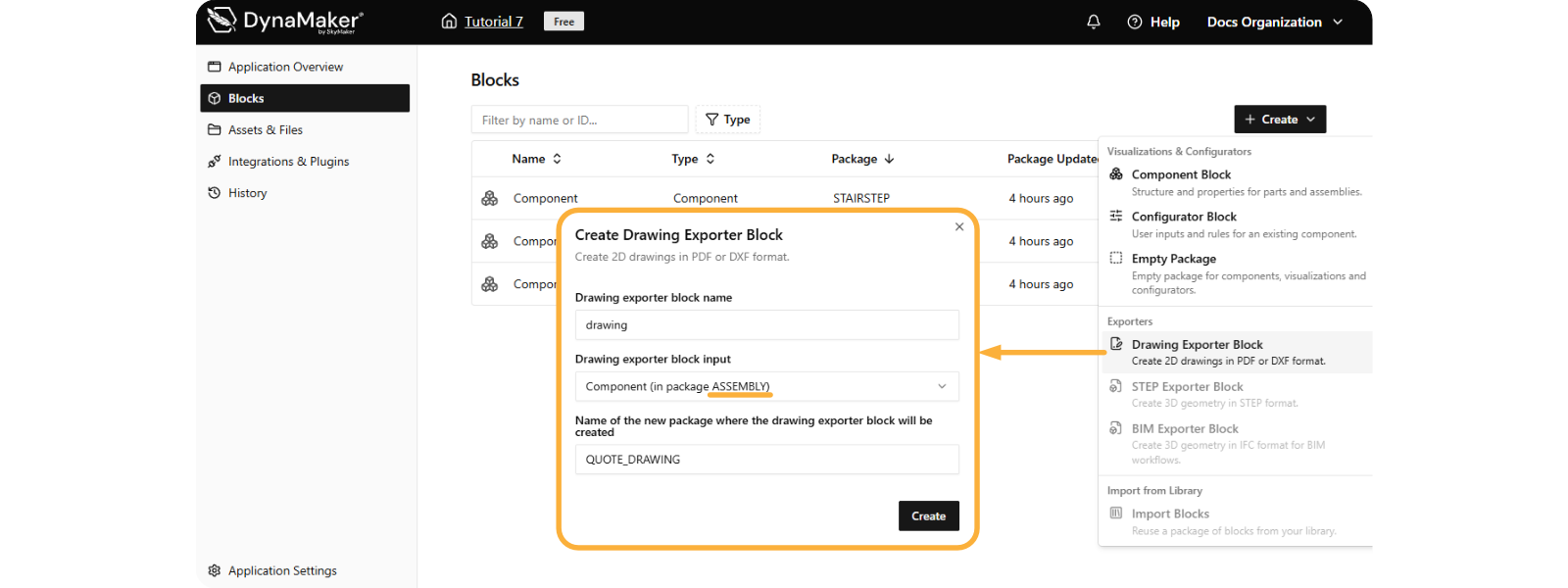
B. Create Exporter
In the app dashboard, Create a Drawing Exporter Block with ASSEMBLY as block input
When you open this QUOTE_DRAWING, you will see the Drawing editor, in this case with the assembly top view:
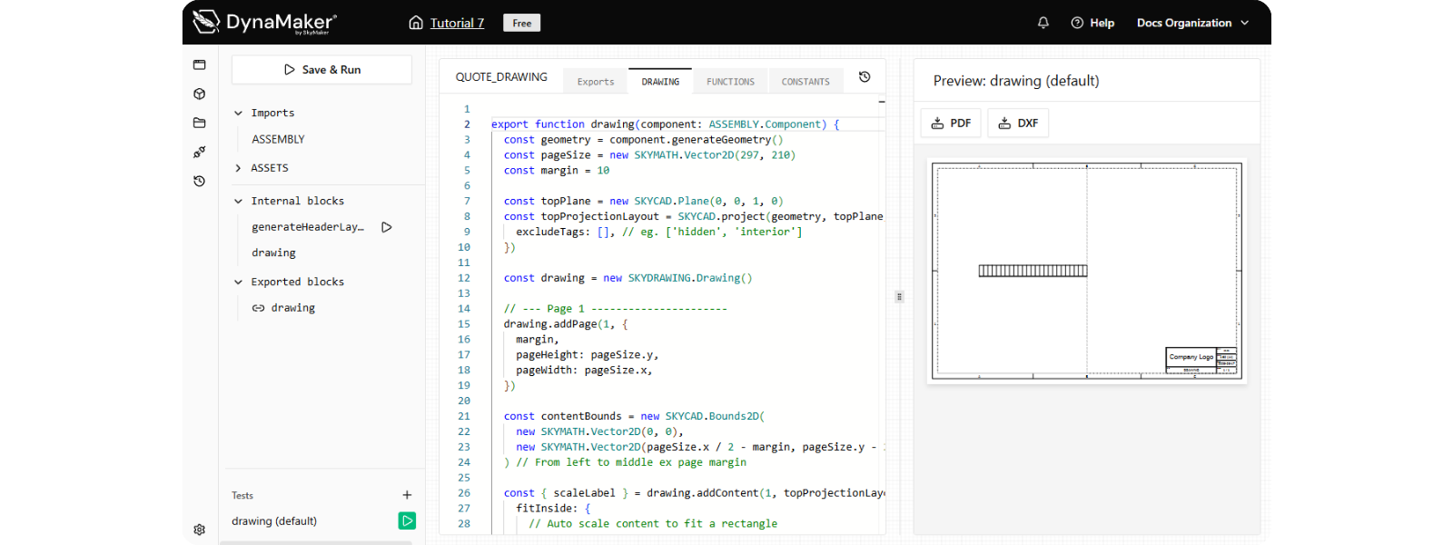
Download your drawing in PDF or DXF format at the top of the preview with 📥 PDF & 📥 DXF.
2. Projections
Let's replace the default top view with the front and side views:
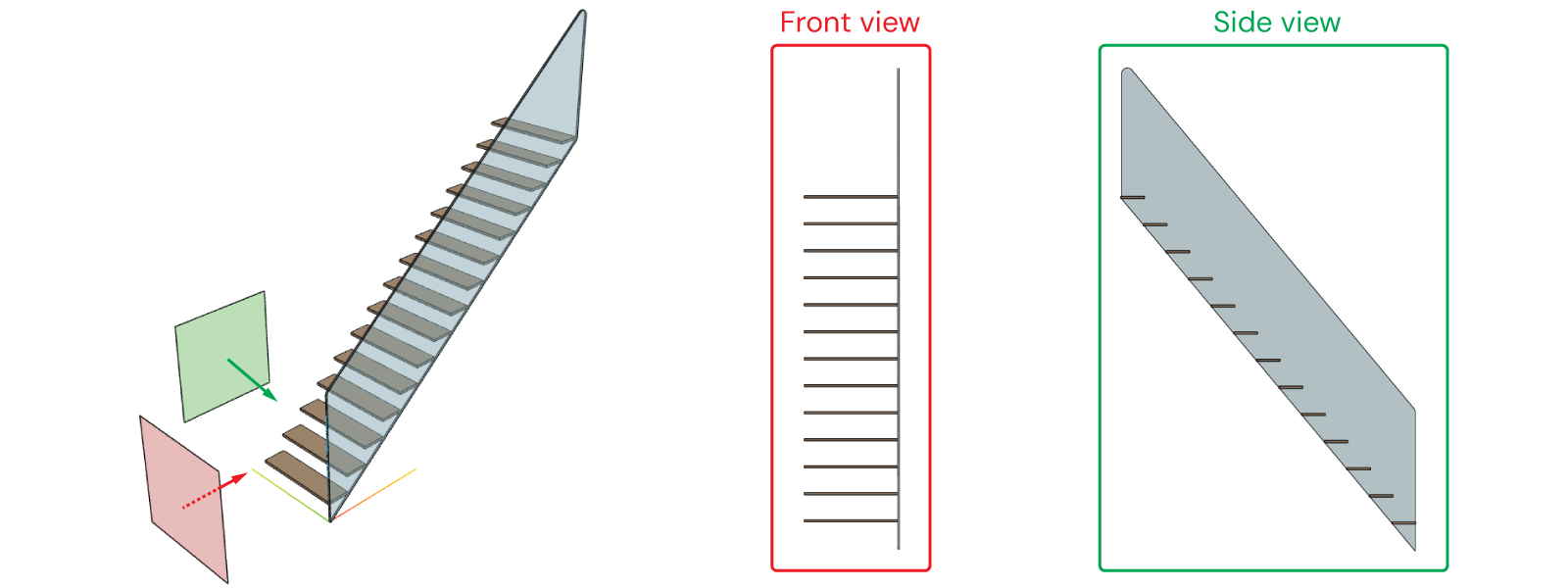
In DynaMaker a CAD projection can be done as follows, resulting in a SKYCAD.Layout:
const projectionLayout = SKYCAD.project(geometry, plane)
A. Update Content
Inside drawing():
-
create a new
contentLayout:const contentLayout = new SKYCAD.Layout() -
create
frontProjectionLayoutwith the respective plane and add it tocontentLayout:const frontPlane = new SKYCAD.Plane(-1, 0, 0, 2000) // offset of 2000 should be enough not to collide with the geometry
const frontProjectionLayout = SKYCAD.project(geometry, frontPlane)
contentLayout.addLayout(frontProjectionLayout) -
get the property
widthfromcomponentat the beginning of the function:export function drawing(component: ASSEMBLY.Component) {
const { width } = component.getProperties()
const geometry = component.generateGeometry()
// ... rest of the function
} -
create
sideProjectionLayoutwith the respective plane and add it tocontentLayoutmoved withwidth:const sidePlane = new SKYCAD.Plane(0, 1, 0, 2000)
const sideProjectionLayout = SKYCAD.project(geometry, sidePlane)
contentLayout.addLayout(sideProjectionLayout, {
position: new SKYMATH.Vector2D(width + 500, 0),
}) -
add an extended
validScalesthat goes e.g. from1:1to1:300with some loop like:const validScales = [1]
for (let i = 2; i < 300; i++) validScales.push(1 / i)tipThese
validScalesindrawing.addContent(layout, { validScales })can also be:validScales: undefinedto autofit to a default list of values that follow the ISO standard.validScales: []to autofit to the max scale (including decimals) that makes the layout fit to the exact bounds.
With the above changes, drawing() should look like the following:
export function drawing(component: ASSEMBLY.Component) {
const { width } = component.getProperties()
const geometry = component.generateGeometry()
// Drawing
const drawing = new SKYDRAWING.Drawing()
const pageSize = new SKYMATH.Vector2D(297, 210)
const margin = 10
// Page 1
let pageNr = 1
drawing.addPage(pageNr, {
pageHeight: pageSize.y,
pageWidth: pageSize.x,
margin,
})
// Content
const contentLayout = new SKYCAD.Layout()
// --- front view
const frontPlane = new SKYCAD.Plane(-1, 0, 0, 2000) // offset of 2000 should be enough not to collide with the geometry
const frontProjectionLayout = SKYCAD.project(geometry, frontPlane)
contentLayout.addLayout(frontProjectionLayout)
// --- side view
const sidePlane = new SKYCAD.Plane(0, 1, 0, 2000)
const sideProjectionLayout = SKYCAD.project(geometry, sidePlane)
contentLayout.addLayout(sideProjectionLayout, {
  position: new SKYMATH.Vector2D(width + 500, 0),
})
// --- content in drawing
const contentBounds = new SKYCAD.Bounds2D( // adjusted so that it doesn't collide with the header
new SKYMATH.Vector2D(margin, margin),
new SKYMATH.Vector2D(0.65 * pageSize.x, pageSize.y - 3 * margin),
)
const validScales = [1]
for (let i = 0; i < 300; i++) validScales.push(1 / i)
const { scaleLabel } = drawing.addContent(pageNr, contentLayout, {
fitInside: {
bounds: contentBounds,
validScales,
},
align: { horizontal: 'center', vertical: 'center' },
})
// Header
const headerLayout = FUNCTIONS.generateHeaderLayout({
title: 'DRAWING',
pageNr,
nPages: drawing.getPages().length,
scale: `${scaleLabel} (A4)`,
})
drawing.setHeader(pageNr, headerLayout)
return drawing
}
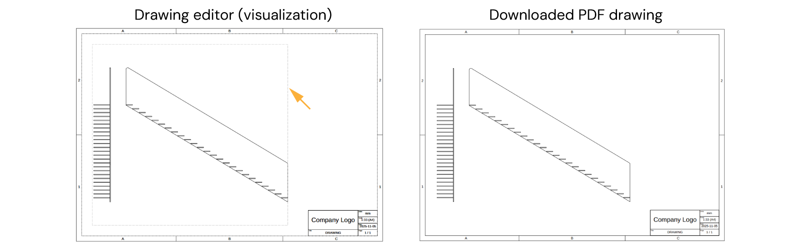
Notice that in the visualization of the drawing editor, the bounds of the content is delimmited by a grey-dashed rectangle sketch.
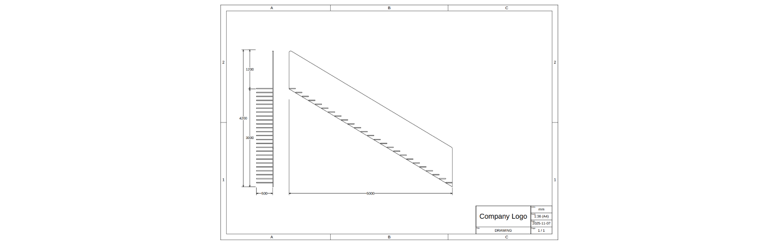
B. Add Dimensions
Dimensions can be added to the geometry so that they will show up with the projection in drawings. However, since we don't want dimensions in the geometry (e.g. later to be used in the visualizaiton) but in the drawing, we will simply add them to the projected layouts.
Dimensions can only be added to layouts as:
const startPoint = new SKYMATH.Vector2D(0, 0)
const endPoint = new SKYMATH.Vector2D(15, 7)
layout.addDimension(startPoint, endPoint)
B1. Front view dimensions
Let's add the dimensions that clearly show the width, height and railingHeight of the staircase in the
projections:
-
Start by getting the rest of the properties at the beginning of
drawing():export function drawing(component: ASSEMBLY.Component) {
const { width, height, railingHeight, depth } = component.getProperties()
const geometry = component.generateGeometry()
// ... rest of the function
} -
Force all text to have size 3 in
drawing.addContent()when addingcontentLayout:const { scaleLabel } = drawing.addContent(1, contentLayout, {
textSize: 3, // <-- all text in contentLayout will have 3 mm in height
fitInside: {
bounds: contentBounds,
validScales,
},
align: { horizontal: 'center', vertical: 'center' },
})- add dimensions for
height,railing, total height anddepthto thefrontProjectionLayoutas:
// --- front view
const frontPlane = new SKYCAD.Plane(-1, 0, 0, 2000)
const frontProjectionLayout = SKYCAD.project(geometry, frontPlane)
// --- a) height:
frontProjectionLayout.addDimension(new SKYMATH.Vector2D(-depth, 0), new SKYMATH.Vector2D(-depth, height), {
offset: 200,
decimals: 0,
})
// --- b) railingHeight:
frontProjectionLayout.addDimension(
new SKYMATH.Vector2D(-depth, height),
new SKYMATH.Vector2D(-depth, height + railingHeight),
{ offset: 200, decimals: 0 },
)
// --- c) total height (height + railingHeight):
frontProjectionLayout.addDimension(
new SKYMATH.Vector2D(-depth, 0),
new SKYMATH.Vector2D(-depth, height + railingHeight),
{ offset: 400, decimals: 0 },
)
// --- d) depth:
frontProjectionLayout.addDimension(new SKYMATH.Vector2D(0, 0), new SKYMATH.Vector2D(-depth, 0), {
offset: 200,
decimals: 0,
})
contentLayout.addLayout(frontProjectionLayout, {
position: new SKYMATH.Vector2D(-depth, 0),
}) - add dimensions for
B2. Side view dimensions
- add
widthdimension tosideProjectionLayout:
// --- side view
const sidePlane = new SKYCAD.Plane(0, 1, 0, 2000)
const sideProjectionLayout = SKYCAD.project(geometry, sidePlane)
sideProjectionLayout.addDimension(new SKYMATH.Vector2D(0, 0), new SKYMATH.Vector2D(-width, height), {
offset: 200,
decimals: 0,
directionOfMeasurement: new SKYMATH.Vector2D(1, 0),
})
contentLayout.addLayout(sideProjectionLayout, {
position: new SKYMATH.Vector2D(width + 500, 0),
})
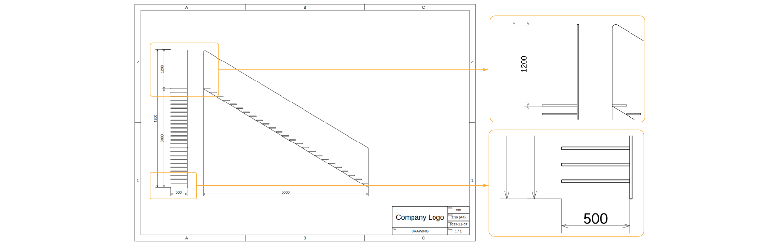
Use dimension optional input directionOfMeasurement when you are only interested in a certain direction e.g.:
- horizontal dimension
new SKYMATH.Vector2D(1, 0) - vertical dimension
new SKYMATH.Vector2D(1, 0) - diagonal at 45deg
new SKYMATH.Vector2D(1, 1)
Notice how the extension lines of the dimension reach both start and end positions of the dimension.
C. Dimensions Style
We will:
- increase the line thickness of the projection.
- decrease the dimensions line thickness.
- make the dimensions with a continuous line.
- make the dimension extension lines reach their points.
The style of a layout can be changed:
- a) when creating the layout:
const layout = new SKYCAD.Layout({
defaultColor: 0xff0000,
defaultSketchLineThickness: 5,
}) - b) after creating a layout with
layout.setDefaultStyle():const layout = new SKYCAD.Layout()
layout.setDefaultStyle({
defaultColor: 0xff0000,
defaultSketchLineThickness: 5,
})
You can try the following style:
// --- front view
const frontPlane = new SKYCAD.Plane(-1, 0, 0, 2000)
const frontProjectionLayout = SKYCAD.project(geometry, frontPlane)
frontProjectionLayout.setDefaultStyle({
defaultDimensionExtensionLineType: 'extended',
defaultDimensionContinuousLines: true,
defaultSketchLineThickness: 5,
defaultDimensionLineThickness: 0.001,
})
// ... rest of front view dimensions
// --- side view
const sidePlane = new SKYCAD.Plane(0, 1, 0, 2000)
const sideProjectionLayout = SKYCAD.project(geometry, sidePlane)
sideProjectionLayout.setDefaultStyle({
defaultDimensionExtensionLineType: 'extended',
defaultDimensionContinuousLines: true,
defaultSketchLineThickness: 5,
defaultDimensionLineThickness: 0.001,
})
// ... rest of side view dimensions
You can explore all the optional input available with Ctrl+Space within
layout.setDefaultStyle({}):

D. Isometric view
An isometric view is nothing more than another projection with a different direction. As you have noticed, projections
are always orthographic. Let's say we want to have a 1 : 80 scale for it and place it slightly above the header (which
has 24 mm of height if you check its size by accessing the bounds of the layout through layout.getBounds().getSize()):
export function drawing(component: ASSEMBLY.Component) {
// Properties & geometry
// Drawing
// Page 1
// Content
// --- front view
// --- side view
// --- content in drawing
// Isometric view
const isoScale = 1 / 80
const isoProjectionLayout = new SKYCAD.Layout()
const isoPlane = new SKYCAD.Plane(-1, 1, 1, 2000)
const projectionLayout = SKYCAD.project(geometry, isoPlane)
isoProjectionLayout.addLayout(projectionLayout)
drawing.addContent(1, isoProjectionLayout, {
position: new SKYMATH.Vector2D(pageSize.x - 2.5 * margin, 40),
scale: isoScale,
textSize: 3,
showScale: true, // <-- shows scale as text at the bottom
})
// Header
return drawing
}
Alternatively you could use the argument fitInside and extract scaleLabel for the header, instead of using a static
scale as we did.
Depending on how realistic you want your drawings to be, you should follow a standard (e.g. ISO 129-1:2018) that determines the rules behind dimensions, view placement, etc. Some of these rules:
- dimension lines must not cross or touch the geometry and should have clear spacing when parallel.
- extension lines may cross each other but not the geometry when possible.
- dimensions should be placed for easy reading, preferably from the bottom or right side.
- dimensions must be clear and non-redundant without confusing the reader.
- dimension and extension lines should be thinner than geometry lines.
- views drawn at a different scale must have that scale shown near the view title.
3. Header
A header is nothing more than a SKYCAD.Table with rows and columns. Each cell is customizable, i.e custom labels, row/column span, color, etc. Here we will add:
- a) picture as a logo
- b) extra column for the projection standard used and the revision number.
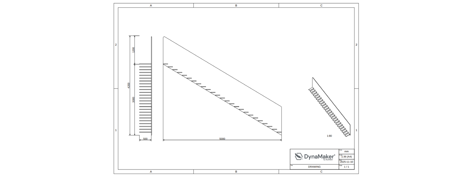
A. Add Logo
- Use any picture for your drawing logo, or use DynaMaker's.
- Go back to the app dashboard.
- In Assets & Files File, click Upload File with name e.g. DYNAMAKER_LOGO_PNG and check Automatically create image assets from image source files.
- Go again into QUOTE_DRAWING, in IMPORTS (top of left sidebar), import
ASSETS. - In FUNCTIONS, go to
generateHeaderLayout()and identify wherelogois defined:let logo: HTMLImageElement | undefined // ASSETS.IMAGES.MY_LOGO_PNG - replace it with your asset:
const logo = ASSETS.IMAGES.DYNAMAKER_LOGO - Save & Run (or Ctrl+S) to see the DynaMaker logo or yours in the header.
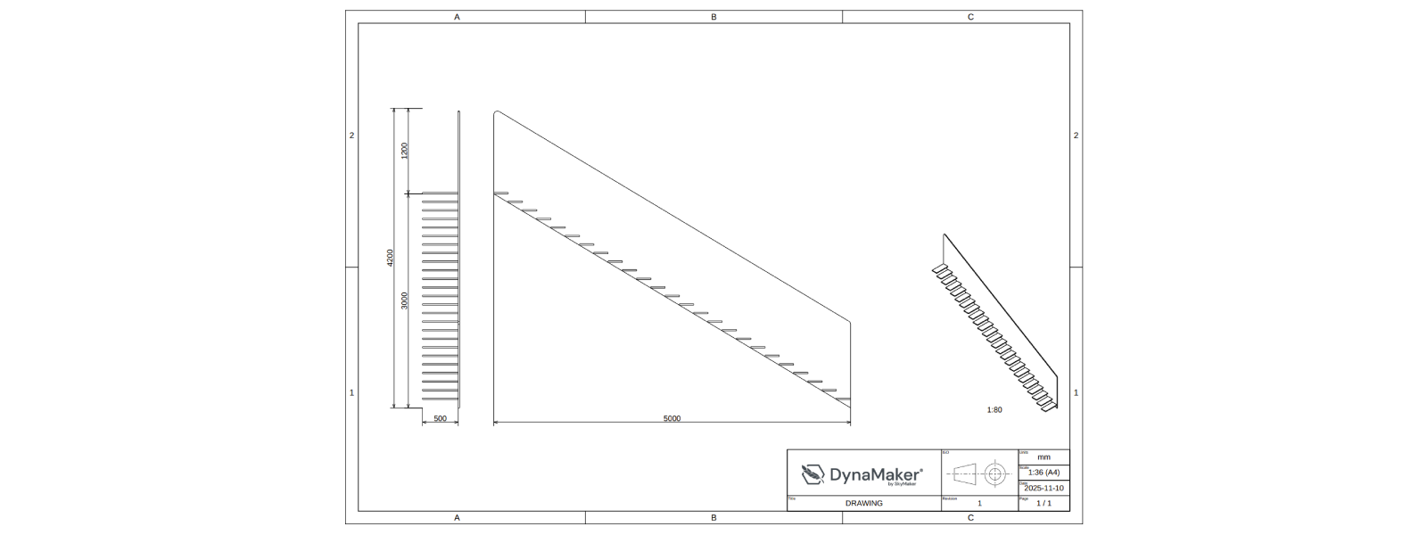
B. Add New Column
We will add an extra column to the table in the middle including two cells:
- one with two rows for showing the projection standard with a picture, i.e. ISO for European.
- one for the revision number, in case later manufacturing changes are approved.
A table is defined by a consistent addition of cells in a specific row and column, starting from the top-left. Example
const table = new SKYCAD.Table()
table.addText('', 0, 0, { rowspan: 3 }) // empty cell, at position 0x0, covering 3 rows (intended for the logo image later).
table.addText('DRAWING', 3, 0, { label: 'Title' }) // cell with static string "DRAWING", at position 3x0, with label "Title".
table.addText(scale, 1, 2, { label: 'Scale' }) // cell with dynamic string "scale", at position 1x2, with label "Scale".
const tableLayout = table.generateLayout() // convert table to layout (e.g. to add images and others).
Feel free to be creative in this part as long as it's clear. See if you can get the following (see solution below picture):
Doublecheck your solution here:
export function generateHeaderLayout({ scale = '', title = 'Staircase' } = {}) {
// Table
const defaultTextSize = 3
const rowHeight = 2 * defaultTextSize
const table = new SKYCAD.Table({
defaultTextSize,
columnWidths: [60, 30, 20],
rowHeights: [rowHeight, rowHeight, rowHeight, rowHeight],
})
// 1st column
table.addText('', 0, 0, { rowspan: 3 })
table.addText(title, 3, 0, { label: 'Title' })
// 2nd column
table.addText('', 0, 1, { label: 'ISO', rowspan: 3 })
table.addText('1', 3, 1, { label: 'Revision' })
// 3rd column
table.addText('mm', 0, 2, { label: 'Units' })
table.addText(scale, 1, 2, { label: 'Scale' })
const dateString = new Date().toISOString().split('T')[0]!
table.addText(dateString, 2, 2, { label: 'Date' })
table.addText('1 / 1', 3, 2, { label: 'Page' })
// Convert to layout
const headerLayout = table.generateLayout()
// Images (logo and ISO standard)
const logo = ASSETS.IMAGES.DYNAMAKER_LOGO
headerLayout.addImage(logo, {
position: new SKYMATH.Vector2D(3, 8),
scale: 0.05,
})
headerLayout.addImage(ASSETS.IMAGES.ISO_STANDARD, {
position: new SKYMATH.Vector2D(62, 9),
scale: 0.032,
})
return headerLayout
}
export function drawing(component: ASSEMBLY.Component) {
// Properties, geometry & SKYDRAWING.Drawing
// Page 1
// Front and side views
// Isometric view
// Header
const headerLayout = FUNCTIONS.generateHeaderLayout({
// title: 'Staircase', // generateHeaderLayout has already a default for title that we can reuse
scale: `${scaleLabel} (A4)`,
})
drawing.setHeader(1, headerLayout)
return drawing
}
See that we have simplified the function by having fixed positions and scales, rather than a smart fitting of the
picture with a dynamic tableRow and such. Sometimes simpler logic helps more than a very smart function.
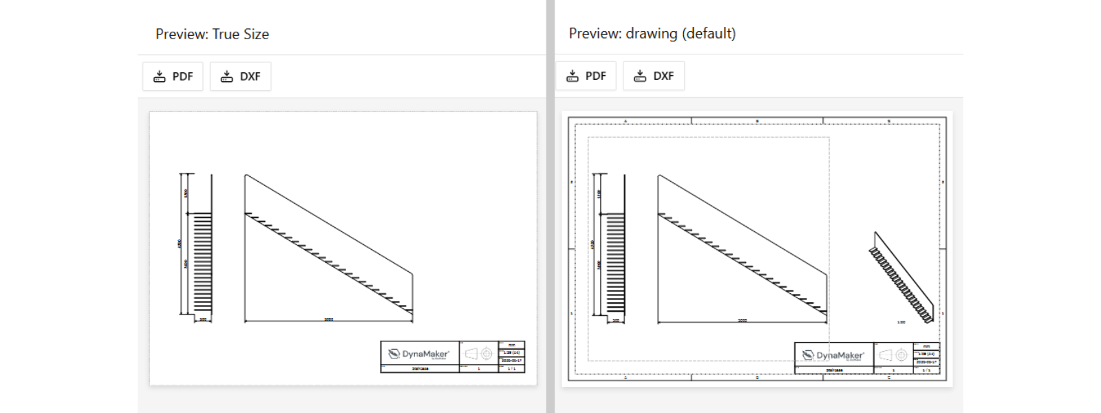
4. True Size
Let's say that Manufacturing wants to have the DXF drawings with true dimensions (i.e. scale 1:1 ), and e.g. without
the isometric projection or drawing frame. You can go with a different drawing exporter for this purpose too, but if
it's just the size of the drawing that will change and toggle some of its content, then we can simply work on the
current drawing().
A. trueSize
- Add
trueSizeas optional input todrawing(), withfalseas default as:
export function drawing(component: ASSEMBLY.Component, { trueSize = false } = {}) {
// rest of function
}
- Remove frame by having an empty layout like
drawing.addPage(1, { frame: new SKYCAD.Layout() })
export function drawing(component: ASSEMBLY.Component, { trueSize = false } = {}) {
// Properties, geometry and SKYDRAWING.Drawing
// Page 1
drawing.addPage(1, {
margin,
pageHeight: pageSize.y,
pageWidth: pageSize.x,
frame: trueSize ? new SKYCAD.Layout() : undefined,
})
// rest of function
}
- Add an if-statement for the isometric view only if
trueSizeisfalse:
export function drawing(component: ASSEMBLY.Component, { trueSize = false } = {}) {
// rest of function
// Isometric view
if (trueSize === false) {
// same as "if (!trueSize) {"
// logic of isometric view
}
// rest of function
}
TypeScript tip for if-conditions:
- in-line to save some space (suitable when only 2 alternatives):
const value = condition ? alternativeA : alternativeB
// same as:
const value = condition ? alternativeA : alternativeB
- most common way (optionally skip
else ifand/orelse)
let value = alternativeA
if (condition1) {
value = alternativeB
} else if (condition2) {
value = alternativeC
} else if (condition3) {
value = alternativeD
} else {
value = alternativeE
}
- common way skipping
{}(suitable for very short logic, optionally skipelse ifand/orelse)
let value = alternativeA
if (condition) value = alternativeB
else if (condition2) value = alternativeC
else if (condition3) value = alternativeD
else value = alternativeE
- Together with
scaleLable, get alsoscaleas output ofdrawing.addContent():
// --- content in drawing
// contentBounds & validScales
const { scale, scaleLabel } = drawing.addContent(1, contentLayout, { // <-- get "scale" too
// rest of arguments
}
- At the end of
drawing(), addif-condition withtrueSizeto rescale entire drawing whentrue:
export function drawing(component: ASSEMBLY.Component, images: HTMLImageElement[], { trueSize = false } = {}) {
// rest of function
if (!trueSize) {
return drawing
} else {
const page1 = drawing.getPages()[0]!
const trueSizeLayout = page1.generateLayout()
trueSizeLayout.scale(1 / scale)
const trueSizeDrawing = new SKYDRAWING.Drawing()
const trueSizePageHeight = pageSize.y / scale
const trueSizePageWidth = pageSize.x / scale
trueSizeDrawing.addPage(1, {
pageHeight: trueSizePageHeight,
pageWidth: trueSizePageWidth,
frame: new SKYCAD.Layout(),
})
trueSizeDrawing.addContent(1, trueSizeLayout)
return trueSizeDrawing
}
}
See that the original drawing is not altered, but rather a copy trueSizeDrawing is created when trueSize = true
- Save & Run to apply changes.
You will not see any changes in the visualization, since the default is trueSize = false. A new test is needed!
B. Clone Test
When introducing a change that is not visible by default, it's best to capture its behavior with a new test. For this:
- at the bottom of the left sidebar, next to Tests, click +.
- select Drawing Test, next to
drawing (default), click ••• and then Clone. - name the test e.g. True size.
- make sure to pass the optional input
trueSize: trueto the new test.
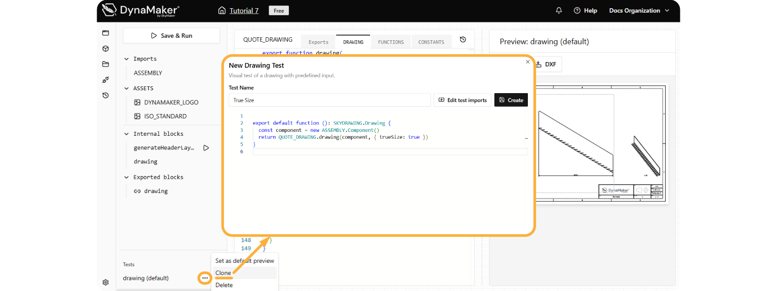
- click Create and switch tests to see the results.
Feel free to download the drawing in DXF format at the top (📥 DXF), open this DXF file with your DXF-viewer software and doublecheck the difference when adding dimensions there.
Doublecheck the solution code here:
export function generateHeaderLayout({ scale = '', title = 'Staircase' } = {}) {
// Table
const defaultTextSize = 3
const rowHeight = 2 * defaultTextSize
const table = new SKYCAD.Table({
defaultTextSize,
columnWidths: [60, 30, 20],
rowHeights: [rowHeight, rowHeight, rowHeight, rowHeight],
})
// 1st column
table.addText('', 0, 0, { rowspan: 3 })
table.addText(title, 3, 0, { label: 'Title' })
// 2nd column
table.addText('', 0, 1, { label: 'ISO', rowspan: 3 })
table.addText('1', 3, 1, { label: 'Revision' })
// 3rd column
table.addText('mm', 0, 2, { label: 'Units' })
table.addText(scale, 1, 2, { label: 'Scale' })
const dateString = new Date().toISOString().split('T')[0]!
table.addText(dateString, 2, 2, { label: 'Date' })
table.addText('1 / 1', 3, 2, { label: 'Page' })
// Convert to layout
const headerLayout = table.generateLayout()
// Images (logo and ISO standard)
const logo = ASSETS.IMAGES.DYNAMAKER_LOGO
headerLayout.addImage(logo, {
position: new SKYMATH.Vector2D(3, 8),
scale: 0.05,
})
headerLayout.addImage(ASSETS.IMAGES.ISO_STANDARD, {
position: new SKYMATH.Vector2D(62, 9),
scale: 0.032,
})
return headerLayout
}
export function drawing(component: ASSEMBLY.Component, { trueSize = false } = {}) {
const { width, height, railingHeight, depth } = component.getProperties()
const geometry = component.generateGeometry()
const pageSize = new SKYMATH.Vector2D(297, 210)
const margin = 10
const drawing = new SKYDRAWING.Drawing()
// --- Page 1 ----------------------
drawing.addPage(1, {
margin,
pageHeight: pageSize.y,
pageWidth: pageSize.x,
frame: trueSize ? new SKYCAD.Layout() : undefined,
})
// Content
const contentLayout = new SKYCAD.Layout()
// --- front view
const frontPlane = new SKYCAD.Plane(-1, 0, 0, 2000) // offset of 2000 should be enough not to collide with the geometry
const frontProjectionLayout = SKYCAD.project(geometry, frontPlane)
frontProjectionLayout.setDefaultStyle({
defaultDimensionExtensionLineType: 'extended',
defaultDimensionContinuousLines: true,
defaultSketchLineThickness: 5,
defaultDimensionLineThickness: 0.001,
})
frontProjectionLayout.addDimension(new SKYMATH.Vector2D(-depth, 0), new SKYMATH.Vector2D(-depth, height), {
offset: 200,
decimals: 0,
})
frontProjectionLayout.addDimension(
new SKYMATH.Vector2D(-depth, height),
new SKYMATH.Vector2D(-depth, height + railingHeight),
{ offset: 200, decimals: 0 },
)
frontProjectionLayout.addDimension(
new SKYMATH.Vector2D(-depth, 0),
new SKYMATH.Vector2D(-depth, height + railingHeight),
{ offset: 400, decimals: 0 },
)
frontProjectionLayout.addDimension(new SKYMATH.Vector2D(0, 0), new SKYMATH.Vector2D(-depth, 0), {
offset: 200,
decimals: 0,
})
contentLayout.addLayout(frontProjectionLayout)
// --- side view
const sidePlane = new SKYCAD.Plane(0, 1, 0, 2000)
const sideProjectionLayout = SKYCAD.project(geometry, sidePlane)
sideProjectionLayout.setDefaultStyle({
defaultDimensionExtensionLineType: 'extended',
defaultDimensionContinuousLines: true,
defaultSketchLineThickness: 5,
defaultDimensionLineThickness: 0.001,
})
sideProjectionLayout.addDimension(new SKYMATH.Vector2D(0, 0), new SKYMATH.Vector2D(-width, height), {
offset: 200,
decimals: 0,
directionOfMeasurement: new SKYMATH.Vector2D(1, 0),
})
contentLayout.addLayout(sideProjectionLayout, {
position: new SKYMATH.Vector2D(width + 500, 0),
})
// --- content in drawing
const contentBounds = new SKYCAD.Bounds2D( // adjusted so that it doesn't collide with the header
new SKYMATH.Vector2D(margin, 0.15 * pageSize.y), // <-- extra adjustment so it doesn't collide with new header
new SKYMATH.Vector2D(0.65 * pageSize.x, pageSize.y - 3 * margin),
)
const validScales = [1]
for (let i = 2; i < 300; i++) validScales.push(1 / i)
const { scale, scaleLabel } = drawing.addContent(1, contentLayout, {
textSize: 3,
fitInside: {
bounds: contentBounds,
validScales,
},
align: { horizontal: 'center', vertical: 'center' },
})
// Isometric view
if (!trueSize) {
const isoScale = 1 / 80
const isoProjectionLayout = new SKYCAD.Layout()
const isoPlane = new SKYCAD.Plane(-1, 1, 1, 2000)
const projectionLayout = SKYCAD.project(geometry, isoPlane)
isoProjectionLayout.addLayout(projectionLayout)
drawing.addContent(1, isoProjectionLayout, {
position: new SKYMATH.Vector2D(pageSize.x - 2.5 * margin, 40),
scale: isoScale,
textSize: 3,
showScale: true,
})
}
const headerLayout = FUNCTIONS.generateHeaderLayout({
scale: `${scaleLabel} (A4)`,
})
drawing.setHeader(1, headerLayout)
if (!trueSize) {
return drawing
} else {
const page1 = drawing.getPages()[0]!
const trueSizeLayout = page1.generateLayout()
trueSizeLayout.scale(1 / scale)
const trueSizeDrawing = new SKYDRAWING.Drawing()
const trueSizePageHeight = pageSize.y / scale
const trueSizePageWidth = pageSize.x / scale
trueSizeDrawing.addPage(1, {
pageHeight: trueSizePageHeight,
pageWidth: trueSizePageWidth,
frame: new SKYCAD.Layout(),
})
trueSizeDrawing.addContent(1, trueSizeLayout)
return trueSizeDrawing
}
}
Congratulations! You have created your first drawing. Having it in an app could look like this (check 📥 Export):
Do you want to have a copy of this app in your team? Let us know at support@dynamaker.com! Remember that everyone has their own way of developing and there are multiple valid ways to do things as long as anyone can understand the code!
Now that you know how to autogenerate drawings dynamically, it is time to explain one more powerful feature before we dive into the app itself, and that is the configurator. Go on to the next tutorial Configurators to learn more!