SKYCAD
This library handles everything related to 2D & 3D geometry, such as:
- Plane
- Sketch
- Layout
- Bounds
- Table
- Parametric Model
- Mesh Model
- Connector
- Color
- Material
- Geometry Group
- Font
- G-code
Plane
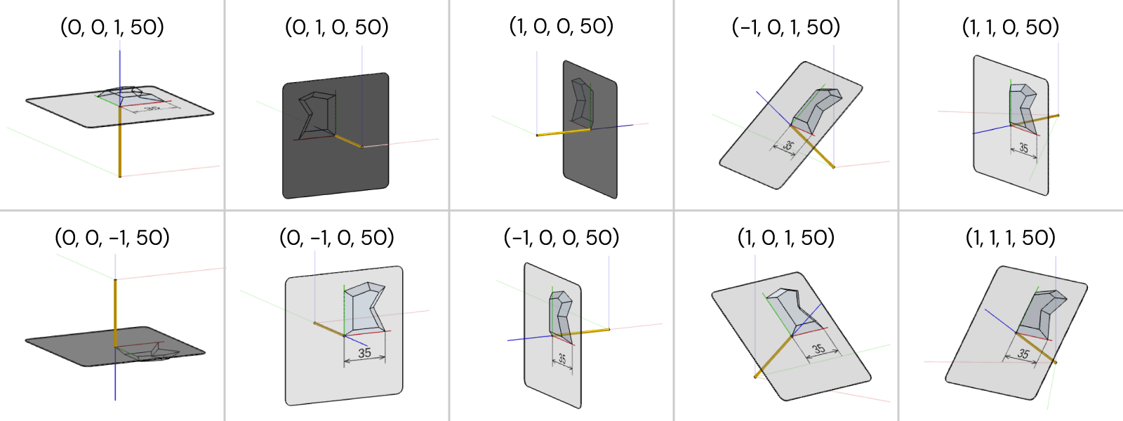
A plane can be used to place geometry in the world or for different 3D operations.
const plane = new SKYCAD.Plane(nX, nY, nZ, offset)
nX,nYandnZare the coordinates of its normal vector (perpendicular to the plane)offsetthe distance from the origin.
Things To Consider
- A plane is not visible in the world
- A plane has its own local coordinate system
- the normal does not need to be a unit vector
offset, which is optional to add handles negative valuesconst defaultPlane = new SKYCAD.Plane()gives you the XY-plane with z-axis pointing upwards.
Uses & Examples
// 3D operations
model.addExtrude(sketch, plane, extrudeLength)
model.addExtrudeCut(sketch, plane, cutLength)
model.addRevolve(sketch, plane)
model.addRevolveCut(sketch, plane)
model.addSplit(plane)

// Placing 2D layouts in 3D
geometryGroup.addGeometry(layout, { plane })

// 2D projections (typically for drawings)
const layout = SKYCAD.project(geometryGroup, plane)
Other
const planeA = new SKYCAD.Plane() // no inputs defined: default plane = (0, 0, 1, 0)
const planeB = new SKYCAD.Plane(0, 0, 1) // no 4th input defined: offset = 0

const clonedPlaneA = planeA.clone()

const normal = planeA.getNormal() // SKYMATH.Vector3D normalized (unit length)
planeA.setNormal(new SKYMATH.Vector3D(1, 0, 0))
planeA.invert() // flips normal
const hasSameNormal = planeA.hasSameNormal(planeB)

const offset = planeA.getOffset() // number
planeA.setOffset(150)

const isEqual = planeA.isEqual(planeB)
const isParallel = planeA.isParallell(planeB)

const point2D = new SKYMATH.Vector2D(15, 20)
const point3D = plane.generatePosition3D(point2D) // returns SKYMATH.Vector3D

const point3D = new SKYMATH.Vector3D(15, 20, -7)
const { positionOnPlane, offset } = plane.generatePosition3D(point3D) // positionOnPlane as SKYMATH.Vector2D
Sketch
Sketches are 2D content that can be used in parametric models and layouts.
How To Create A Sketch
const sketch = new SKYCAD.Sketch()
There are 3 ways of creating a sketch:
By Moving Marker
const myTriangleSketch = new SKYCAD.Sketch()
myTriangleSketch.moveTo(0, 0)
myTriangleSketch.lineTo(100, 0)
myTriangleSketch.curveTo(100, 50, { clockwise: true })
myTriangleSketch.lineToId(0)

lineToId(0)ensures a closed path by going to the node0with a line. Useful to avoid possible bugs in 3D geometries that need a closed contour. Same applies forcurveToId(0).
All curves are counter-clockwise defined by default (
clockwise: false).
By Node Reference
const myTriangleSketch = new SKYCAD.Sketch()
const n0 = myTriangleSketch.addNode(0, 0)
const n1 = myTriangleSketch.addNode(100, 0)
const n2 = myTriangleSketch.addNode(100, 50)

myTriangleSketch.addLine(n0, n1)
myTriangleSketch.addCurve(n1, n2)
myTriangleSketch.addLine(n2, n0)

In order to have a closed contour the sketch needs to return to the first node from which it started.
By Reusing Static Asset
When you have your sketch as DXF file precreated typically from other CAD softwares.
const sketch = ASSETS.STATIC_SKETCHES.DYNAMAKER_LOGO
Read more about static sketches here.
CAD features
In DynaMaker there are 7 CAD features available for sketches:
Polygons
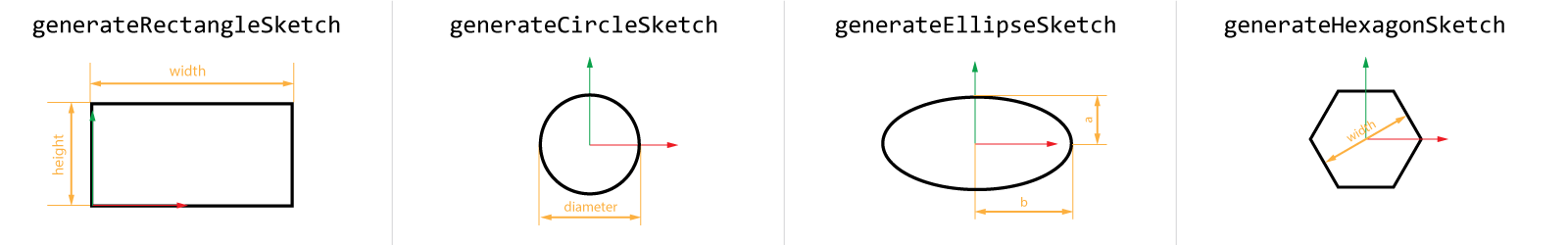
You can create a full closed sketch with the shapes of rectangles, circles, ellipses and regular hexagons like:
const rectangulleSketch = SKYCAD.generateRectangleSketch(posX, posY, width, height)
const circleSketch = SKYCAD.generateCircleSketch(posX, posY, diameter)
const ellipseSketch = SKYCAD.generateEllipseSketch(a, b)
const hexagonSketch = SKYCAD.generateHexagonSketch(posX, posY, width)
If you have a list of nodes (SKYMATH.Vector2D), then you can autogenerate a polygon out of it easily with:
const nodesList = [
  new SKYMATH.Vector2D(0, 0),
  new SKYMATH.Vector2D(5, 0),
  new SKYMATH.Vector2D(7, 10),
  new SKYMATH.Vector2D(-2, 7),
]
const polygonSketch = SKYCAD.generatePolygonSketch(nodesList, { closed: true })
// "closed: true" ensures lineToId(0) or curvedToId(0) is used at the end.
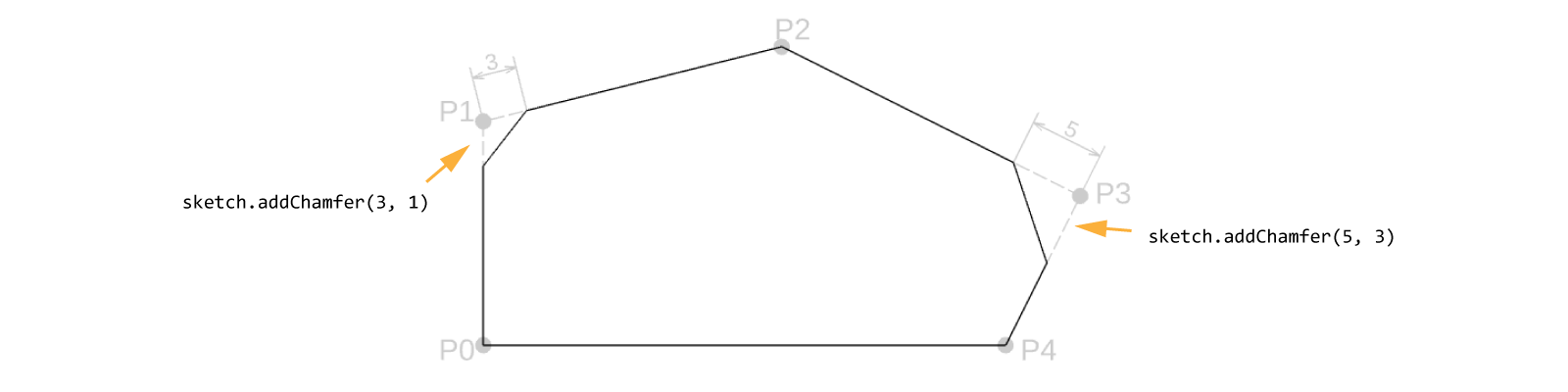
Chamfer
Chamfers are easiest when applied last.
const sketch = SKYCAD.generateRectangleSketch(0, 0, 20, 30)
sketch.addChamfer(3, 1) // chamfer size of 3, applied to node 1
sketch.addChamfer(5, 3) // chamfer size of 5, applied to node 3
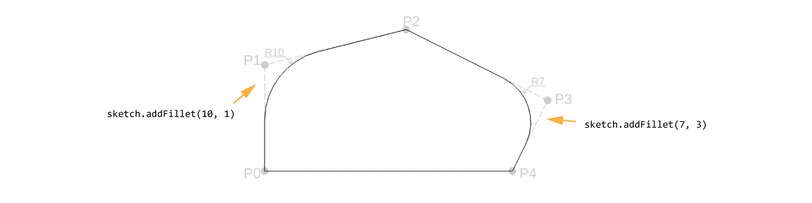
Fillet
Fillets are easiest when applied last.
const sketch = SKYCAD.generateRectangleSketch(0, 0, 20, 30)
sketch.addFillet(10, 1) // fillet with radius 10, applied to node 1
sketch.addFillet(7, 3) // fillet with radius 7, applied to node 3
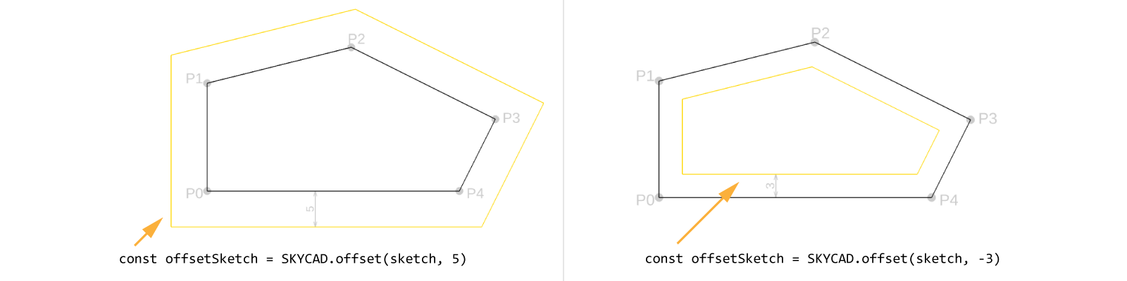
Offset
const offset = 10 // positive builds to the right, negative to the left
const offsetSketch = SKYCAD.offset(openOrClosedSketch, offset)
Bézier curve
In DynaMaker a curve can be treated as a Quadratic Bézier curve, which is defined by 3 points (start, end and control) and their weights (defining the degree of tangency). Combining these properties, each point (A, B, etc) can be drawn using De Casteljau's algorithm, resulting in the desired curve.

There are different optional arguments to use in sketch.curveTo():
radiusof the curve.clockwiseas a boolean to set the curve clockwise (true) or counterclockwise (false).controlPositionas control, defining the tangency towards the start and end of the curvecontrolPositionWeightto set the weight of the point control.startNodeWeightto set the weight of the point start.startNodeWeightto set the weight of the point end.fromNodeIdto specify from which point id the curve should startpointToPassto force the curve to pass through a specified point
Examples of use:
// Most common
sketch.curveTo(0, 10, { radius: 3.5, clockwise: false })
// Typical quadratic Bézier curve
sketch.curveTo(0, 10, {
  controlPosition: new SKYMATH.Vector2D(20, 20),
  controlPositionWeight: 0.5,
  startNodeWeight: 2,
  endNodeWeight: 0.1,
})
Sketch From Bounds
const sketch = SKYCAD.generateSketchFromBounds(bounds2D) // generates a rectangular sketch from SKYCAD.Bounds2D
Sketch From Text
const sketch = SKYCAD.generateSketchFromText('ABCDEF', {
  align: 'center',
  textSize: 50,
})
Remember that
SKYCAD.generateSketchFromText()generates a sketch, therefore it can be used for models.
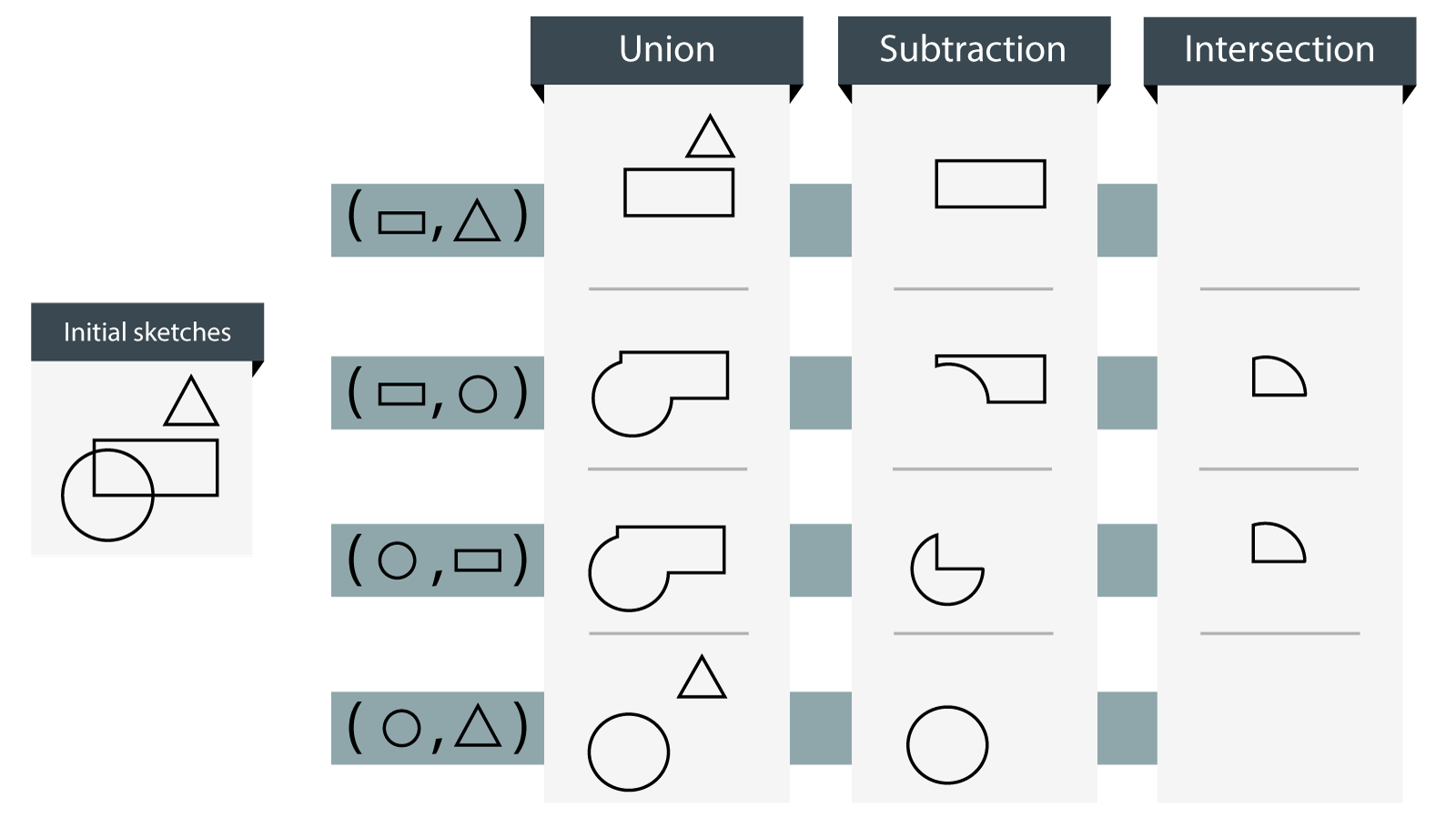
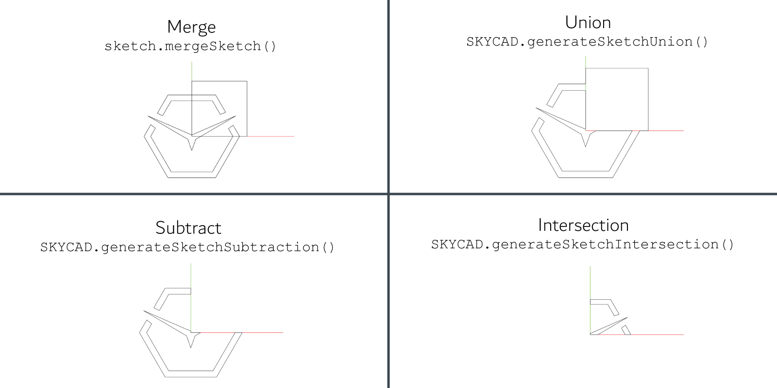
Boolean Operations
Boolean operations can be done between sketches. Create a new sketch as a result of a boolean operation as:
const unionSketch = SKYCAD.generateSketchUnion(sketchA, sketchB)
const subtractionSketch = SKYCAD.generateSketchSubtraction(sketchA, sketchB)
const intersectionSketch = SKYCAD.generateSketchIntersection(sketchA, sketchB)
Example
If you want to merge two different sketches into a single one, regardless of their interaction, you should do
sketchA.mergeSketch(sketchB)instead.
Sketch Troubleshooting
Sometimes when we use sketches that have been generated in external softwares, there can be unknown errors in the
exporting process that damages the sketch in terms of not joining the nodes correctly and therefore not creating a
closed contour which is essential to have for extrusion and other CAD features. However, there are also some mistakes
that can be corrected if a sketch is generated in DynaMaker (SKYCAD.Sketch). These are some of the cases you can try
to fix your sketches:
sketch.mergeOpenEnds()
Some sketches are not fully connected after importing them into the app dashboard and creating a static sketch from
them. Try sketch.mergeOpenEnds() function to connect the lines in the sketch.
const model = new SKYCAD.ParametricModel()
const staticSketch = ASSETS.STATIC_SKETCHES.MY_STATIC_SKETCH
staticSketch.mergeOpenEnds()
model.addExtrude(staticSketch, new SKYCAD.Plane(), 100)
If the extrude still does not work, try lowering the precision of the merge with the decimals option:
const model = new SKYCAD.ParametricModel()
const staticSketch = ASSETS.STATIC_SKETCHES.MY_STATIC_SKETCH
staticSketch.mergeOpenEnds({ decimals: 4 })
model.addExtrude(staticSketch, new SKYCAD.Plane(), 100)
Create Preset 2D
By creating a preset 2D we can see the sketch and see whether the sketch at least is visible or not.
Coming the sketch from a file (i.e. as static sketch), if we don't see the sketch it could be that:
- the sketch is too small: the scale might be wrong due to using e.g. inches or metres instead of millimetres. Doing a
final scale in the sketch with a large number (
sketch.scale(100)) could help with its visualization. - the file is damaged or corrupted: exporting a sketch as DXF could lead to potential errors that DynaMaker can't handle. Usually rexporting the file with certain settings solves it.
Coming the sketch from a DynaMaker function (i.e. as SKYCAD.Sketch), if we don't see the sketch it could be that:
- the function returns an empty sketch or
undefinedfor certain properties or conditions. Debugging helps to identify a problem that usually is due to missing some logic.
sketch.generateDiagnostics()
If we tried sketch.mergeOpenEnds(), created a preset 2D and we still see that the sketch looks correct and "closed",
we can generate some diagnostics and really see whether the sketch is open or not. For that you can simply type
sketch.generateDiagnostics() and/or console.log(sketch.generateDiagnostics()) to see in details the sketch. As
examples of diagnostics from a sketch containing a closed rectangle and an open line:
// Rectangle
----Diagnostics-----
Nodes: 4
Elements: 4
Open contours: 0
Closed contours: 1
Element with open ends: 0
Unconnected nodes: 0
Intersecting elements: 0
Duplicate nodes: 0
Short elements: 0
Zero length elements: 0
// Line
----Diagnostics-----
Nodes: 2
Elements: 1
Open contours: 1
Closed contours: 0
Element with open ends: 2
Unconnected nodes: 0
Intersecting elements: 0
Duplicate nodes: 0
Short elements: 0
Zero length elements: 0
See that Open contours should be 0 if we want to use that sketch for boolean operations or CAD features.
Remove noise
Usually by now you should have identified the problem, either through a preset and/or by generating diagnostics of the sketch. You can then remove the "noise" or those elements/nodes that are hanging and not connected to anything. Knowing that an element is what joins two different nodes, you can try to use the following functions:
sketch.removeZeroLengthElements() // removes all elements that have 0 length (e.g. when 2 nodes at the exact position are connected by an element)
sketch.removeUnusedNodes() // removes nodes that are not being used (i.e. no element connected to them, duplicated nodes by errors)
sketch.removeFreeEndElements() // removes all elements that have a end node not connected to anything
If you tried all these methods and still can't find where the bug is located, you can reach support@dynamaker.com and we will help you to identify the problem exactly!
Other
sketch.translate(5, 5) // 2D translation as (X, Y)
sketch.rotate(Math.PI / 4) // [rad], rotation around the origin (0, 0) of the sketch
sketch.scale(10) // scales the skech from its center, negative values are also accepted
const clonedSketch = sketch.clone() // creates a copy
Rotation & translation are cumulative operations. If you write
sketch.translate(1, 3)and aftersketch.translate(-5, 10), this will result insketch.translate(-4, 13). Same applies for rotation.
For advanced checking, you can see if any item is a SKYCAD.Sketch with:
const isItemSketch = SKYCAD.isSketch(item) // returns true if item is a SKYCAD.Sketch
Layout
Layouts are containers of 2D content to be displayed in geometries or drawings.
How To Create A Layout
const layout = new SKYCAD.Layout()
Content
The following content types can be added to a layout:
Sketches
A SKYCAD.Sketch can be added to a layout as:
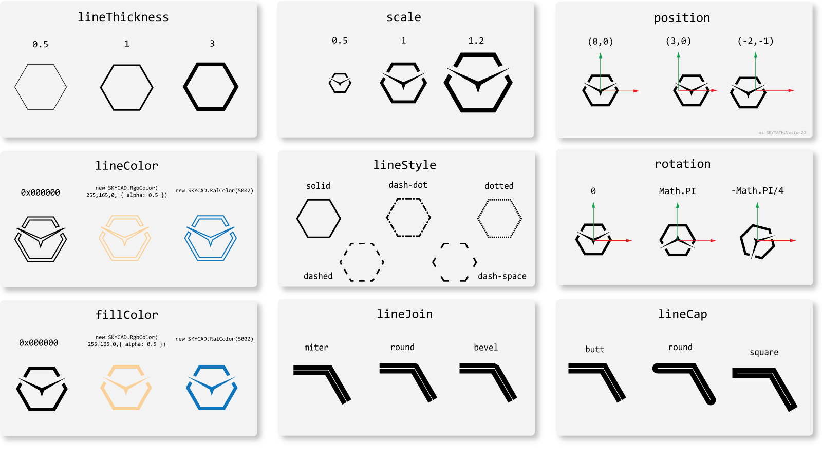
layout.addSketch(sketch, {
  lineThickness: 1,
  lineColor: 0x000000,
  fillColor: 0x000000,
  lineStyle: 'solid', // 'solid' | 'dash-dot' | 'dotted' | 'dashed' | 'dash-space'
  lineJoin: 'miter', // 'miter' | 'round' | 'bevel'
  lineCap: 'butt', // 'butt' | 'round' | 'square'
  position: new SKYMATH.Vector2D(0, 0),
  rotation: 0,
  scale: 1,
})
where its optional arguments could have the following values:
You can also set certain extra settings that apply to sketches at a layout level:
const layout = new SKYCAD.Layout({
  defaultColor: 0x000000, // overrides everything in layout without assigned color-related setting
  defaultTextColor: 0x000000, // overrides everything in layout without assigned textColor setting
  defaultLineStyle: 'dashed', // overrides everything in layout without assigned lineStyle setting

  defaultSketchLineColor: 0x000000,
  defaultSketchFillColor: 0x000000,
  defaultSketchLineStyle: 'solid',
  defaultSketchLineJoin: 'miter',
  defaultSketchLineCap: 'butt',
  defaultSketchLineThickness: 1,
})
Dimensions
A dimension can be added to a layout as:
const startNode = new SKYMATH.Vector2D(0, 0)
const endNode = new SKYMATH.Vector2D(100, 0)
layout.addDimension(startNode, endNode)
where its optional arguments could have the following values:
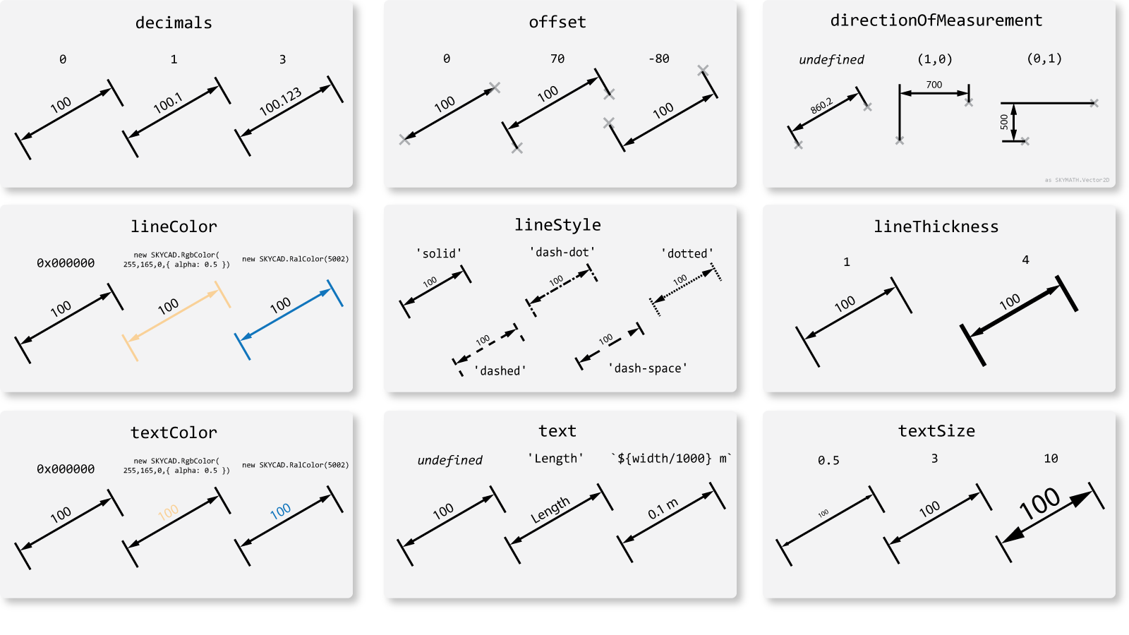
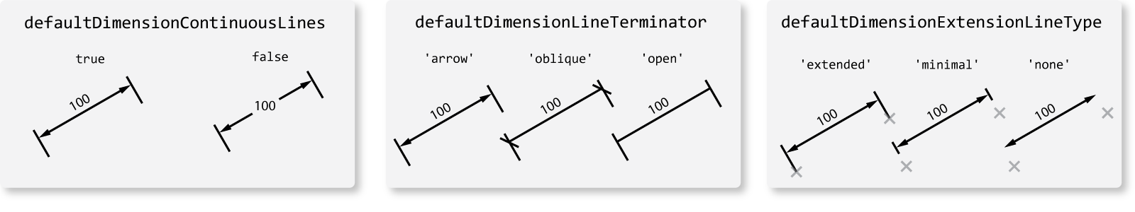
You can also set certain extra settings that apply to dimensions at a layout level:
const layout = new SKYCAD.Layout({
  defaultColor: 0x000000, // overrides everything in layout without assigned color-related setting
  defaultTextColor: 0x000000, // overrides everything in layout without assigned textColor setting
  defaultLineStyle: 'dashed', // overrides everything in layout without assigned lineStyle setting

  defaultDimensionLineColor: 0x000000,
  defaultDimensionTextColor: 0x000000,
  defaultDimensionLineStyle: 'solid',
  defaultDimensionLineThickness: 1,
  defaultDimensionTextRotation: 'aligned' // aligns text with dimension line when defaultDimensionContinuousLines: false. Other regular numbers can also work as input.

  defaultDimensionLineTerminator: 'arrow' // 'arrow' | 'oblique' | 'open'
  defaultDimensionExtensionLineType: 'standard' // 'extended' | 'minimal' | 'none'
  defaultDimensionContinuousLines: true
  defaultFontId: // see https://docs.dynamaker.com/library-skycad#font
})
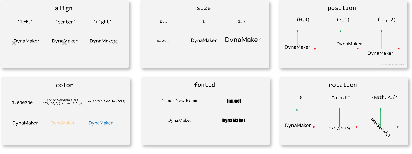
Text
Any text as string can be added to layout as:
layout.addText('DynaMaker')
layout.addText(`Width: ${this.properties.width / 1000} m`) // would result into "Width: 0.1 m" for width = 100.
where its optional arguments could have the following values:
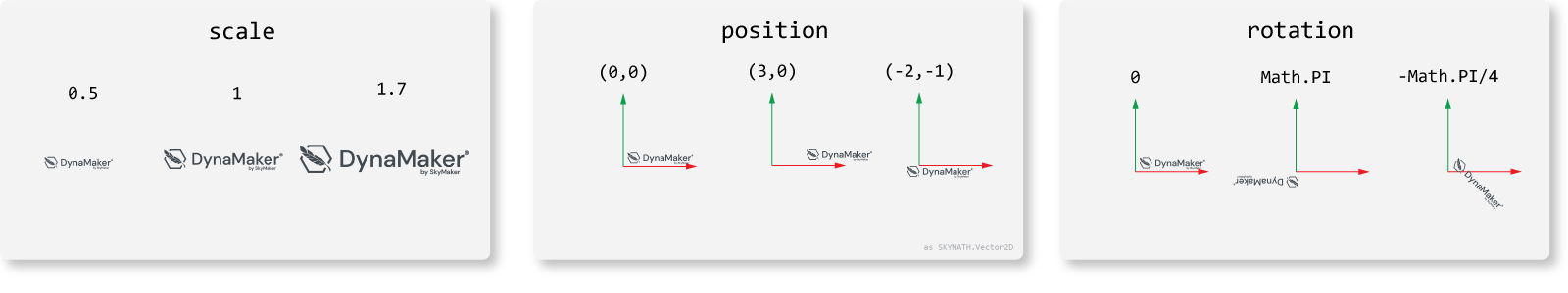
Images
An image is a HTMLImageElement handled through
its URL. Either:
- use any of your pictures created from your dashboard files:
const image = ASSETS.IMAGES.DYNAMAKER_LOGO
layout.addImage(image)
- or if you have the URL directly since you might have it externally storaged somewhere
const image = document.createElement('img')
image.src = 'https://picsum.photos/200/300' // equivalent of ASSETS.URLS.DYNAMAKER_LOGO_PNG
layout.addImage(image)
where its optional arguments could have the following values:
Layouts
You can add a SKYCAD.Layout into other layouts as
layout.addLayout(otherLayout, {
  position: new SKYMATH.Vector2D(10, 3)
  rotation: 10
})
This can be typically found in
SKYDRAWING.Drawingwhen other layouts (e.g.sideViewLayout,frontViewLayout) are typically added to a parent layout (e.g.viewsLayout) so that they can be handled altogether more easily. Or perhaps you have created your custom dimension layout and it's added repeatedly throughout a parent layout.
crop
layout.crop(bounds2D, {
  // modifies layout
  keepDimensions: false, // removes dimensions that get cropped by bounds
  keepTexts: false, // removes texts that get cropped by bounds
})
If you want to crop a layout with any shape instead of rectangular bounds, it needs to be done a bit differently. Instead the crop is applied to each sketch and an extra step is needed when cropping the layout.
const layout = new SKYCAD.Layout()

const lineSketchToCrop = new SKYCAD.Sketch()
lineSketchToCrop.moveTo(0, 0)
lineSketchToCrop.lineTo(100, 100)

const circleSketch = SKYCAD.generateCircleSketch(50, 50, 25)

const cropShapes = circleSketch.generateShapes()
for (const shape of shapes) {
  sketchToCrop.crop(shape, { inverted: true })
}
layout.addSketch(lineSketchToCrop)
Anchors
Anchor positions let you place elements in a layout easily. Add anchors by giving a unique id and position. Sketches, dimensions, and images can be linked via the optional anchor argument.
layout.addAnchor('top-right-sketch', new SKYMATH.Vector2D(10, 7))
layout.addAnchor('bottom-left-dimension', new SKYMATH.Vector2D(-12, 2))
layout.addAnchor('center-layout', new SKYMATH.Vector2D(0, 5))

layout.addSketch(sketch, { anchor: 'top-right-sketch' })
layout.addImage(image, { anchor: 'bottom-left-dimension' })
layout.addLayout(otherLayout, { anchor: 'center-layout' })

const layoutAnchors = layout.getAnchors() // returns anchors as a list
Other
There are functionilities that help you move, rotate or scale the content altogether within the layout:
layout.rotateContent(Math.PI / 4) // [rad], rotation around the perpendicular axis
layout.scaleContent(4) // scales the content, negative values are also accepted
layout.translateContent(5, -3) // 2D translation of content as (X,Y)
const clonedLayout = layout.clone() // creates a copy
There are also functions that help you remove certain of its content. Perhaps you might have a layout already, but you
want the exact same without dimensions or texts. Remember to do a clone (layout.clone()) to avoid undesired bugs.
layout.removeSketchAndSketchInstances()
layout.removeDimensions()
layout.removeTexts()
layout.removeAnchors()
If you have already created your layout, you can still adjust these default settings as follows:
const layoutStyle1 = layout1.getDefaultStyle()

layout2.setDefaultStyle({ defaultColor... }) // adjust any setting individually
layout2.setDefaultStyle(layoutStyle1) // assign other layout's style
For advanced checking, you can see if any item is a SKYCAD.Layout with:
const isItemLayout = SKYCAD.isLayout(item) // returns true if item is a SKYCAD.Layout
Bounds
We defined the bounds as an object containing the position of two corners.
How To Create Bounds
const bounds2D = new SKYCAD.Bounds2D(new SKYMATH.Vector2D(1, 3), new SKYMATH.Vector2D(10, -7))

const bounds3D = new SKYCAD.Bounds3D(new SKYMATH.Vector3D(1, 3, -5), new SKYMATH.Vector3D(10, -7, 8))
Get Bounds
const sketchBounds2D = sketch.getBounds()
const layoutBounds2D = layout.getBounds()
const modelBounds3D = model.getBounds()
const geometryBounds3D = geometryGroup.getBounds()

Collision Detection
const isPositionInsideBounds = bounds.checkPositionInside(position)
const isBoundsAInsideBoundsB = boundsA.isFullyInsideBounds(boundsB)
const isOverlapping = boundsA.isOverlappingBounds(boundsB, { treatTangencyAsOverlap: true })
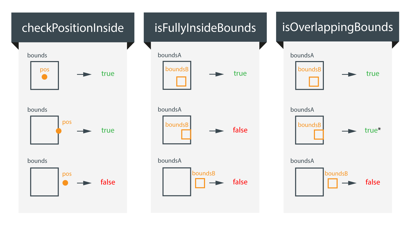
For the second case of
isOverlappingBounds(), the result depends ontreatTangencyAsOverlap, which is set totrueby default.
Other
const clonedBounds = bounds.clone() // creates a copy
bounds.translate(exampleVector) // translation as new SKYMATH.Vector2D(X, Y)
bounds.offset(10) // extends the bounds 10 mm from the center
const size = bounds.getSize() // gives the width (x) and height (y) as: { x: number, y: number }
const centerPosition = bounds.getCenter() // gives the center position
const mergedBounds2D = SKYCAD.mergeBounds2D([bounds2D_A, bounds2D_B, ...]) // merges all 2D bounds into a single SKYCAD.Bounds2D
const mergedBounds3D = SKYCAD.mergeBounds3D([bounds3D_A, bounds3D_B, ...]) // merges all 3 bounds into a single SKYCAD.Bounds3D
const mergedBounds2D = SKYCAD.mergeBounds2D([bounds2D_A, bounds2D_B, ...]) // merges all 2D bounds into a single SKYCAD.Bounds2D
const mergedBounds3D = SKYCAD.mergeBounds3D([bounds3D_A, bounds3D_B, ...]) // merges all 3 bounds into a single SKYCAD.Bounds3D
Table
Tables are great for displaying organized data, such as BOM-lists or headers for your drawings. A table can contain text, images and sketches and any cell can span any number of rows and columns.
Example
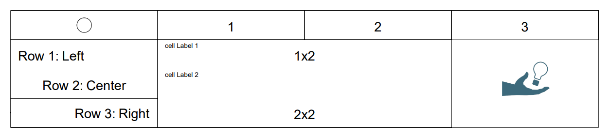
const table = new SKYCAD.Table({ defaultTextSize: 10, width: 400 })

table.addText('1', 0, 1)
table.addText('2', 0, 2)
table.addText('3', 0, 3)

table.addText('Row 1: Left', 1, 0, { align: 'left' })
table.addText('Row 2: Center', 2, 0)
table.addText('Row 3: Right', 3, 0, { align: 'right' })

table.addText('1x2', 1, 1, { colspan: 2, label: 'Cell Label 1' })
table.addText('2x2', 2, 1, { colspan: 2, rowspan: 2, label: 'Cell Label 2' })

table.addSketch(SKYCAD.generateCircleSketch(5, 5, 10), 0, 0)

const tableLayout = table.generateLayout()

tableLayout.addImage(ASSETS.IMAGES.SKYMAKER_LOGO, { position: new SKYMATH.Vector2D(380, 20) })
Notice that the table is converted to a layout with
table.generateLayout(), so it can be added later to other layouts or drawings.
How To Create A Table
Create a table as:
const table = new SKYCAD.Table({
  defaultTextSize: number, // default: 10
  width: number, // default: 512
})
A table can be converted into a sketch by using const layout = table.generateLayout().
The cell size is defined dynamically with its content. The rows and columns of a table will always stretch to fill the full width of the table.
Content
Content is added into a specific row and column. Supported content types are text, images and sketches.
Table coordinates are 0 indexed.
(0, 1)corresponds to first row and second column
Text
// adding 'some text' to the second cell on the first row
table.addText('some text', 0, 0)
table.addText(text: string, row: number, column: number, {
  label?: string,   // default: ''
  colspan?: number, // default: 1, nr of columns to cover
  rowspan?: number, // default: 1, nr of rows to cover
  align?: string,   // default: 'left', ['left', 'center', 'right']
}): void
Sketches
// adding a sketch to the second cell on the first row
table.addSketch(sketch, 0, 0)
table.addSketch(sketch: SKYCAD.Sketch, row: number, column: number, {
  label?: string,   // default: ''
  colspan?: number, // default: 1, nr of columns to cover
  rowspan?: number, // default: 1, nr of rows to cover
}): void
Other
const isItemTable = SKYCAD.isTable(item) // returns true if item is a SKYCAD.Table
Parametric Model
A parametric model is a pure 3D representation, without any information about its material or position. Create a model as:
const model = new SKYCAD.ParametricModel()
CAD Features
In DynaMaker there are 10 CAD features available for models:
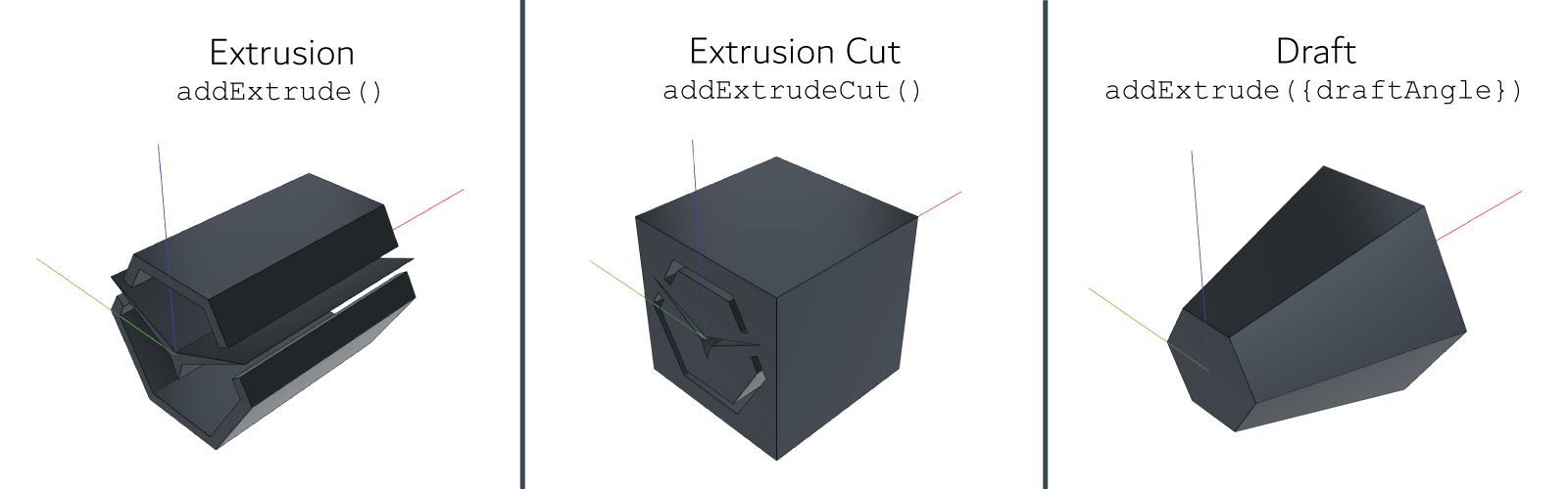
Extrusion
model.addExtrude(sketch, plane, extrusionLength)
Extrusion Cut
model.addExtrudeCut(sketch, plane, extrusionCutLength)
Draft
model.addExtrude(sketch, plane, extrusionLength, { draftAngle })
The following examples use the same sketch and reference plane:
const model = new SKYCAD.ParametricModel()
const plane = new SKYCAD.Plane(1, 0, 0, 0)
const draftAngle = (30 * Math.PI) / 180 // [30 deg]
Edge Modifiers
CAD operations like chamfer can be applied at the start and end of the extrusions like:
model.addExtrude(sketch, plane, extrusionLength, {
  edgeModifierEnd: { type: 'chamfer', size: 5 },
  edgeModifierStart: { type: 'chamfer', size: 10 },
})
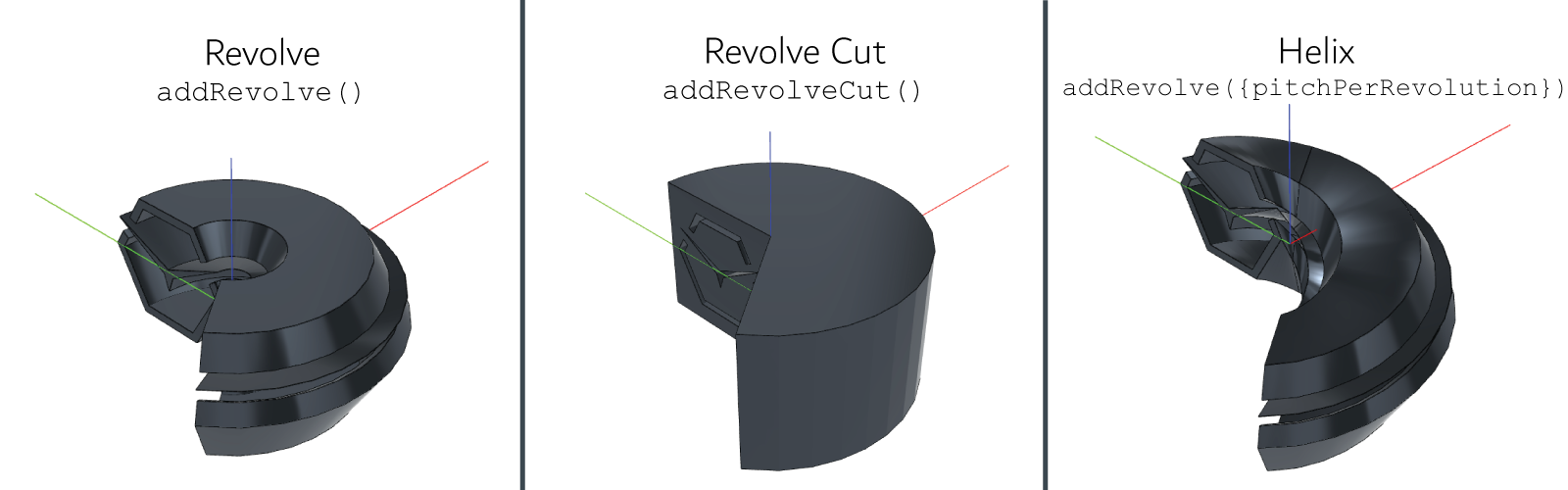
Revolve
model.addRevolve(sketch, plane, { axisDirection, revolveAngle })
Revolve Cut
model.addRevolveCut(sketch, plane, { axisDirection, revolveAngle })
Helix
model.addRevolve(sketch, plane, { axisDirection, revolveAngle, pitchPerRevolution })
model.addRevolveCut(sketch, plane, { axisDirection, revolveAngle, pitchPerRevolution })
The following examples use the same sketch and reference plane:
const model = new SKYCAD.ParametricModel()
const plane = new SKYCAD.Plane(1, 0, 0, 0)
const axisDirection = new SKYMATH.Vector2D(0, -1)
const draftAngle = (30 * Math.PI) / 180 // [30 deg]
const revolveAngle = (235 * Math.PI) / 180 // [235 deg]
Split
const model = new SKYCAD.ParametricModel()
const extrusionPlane = new SKYCAD.Plane(1, 0, -50, 100)
model.addExtrude(sketch, extrusionPlane, 100)

const splitPlane = new SKYCAD.Plane(1, 0, -0.75, 0)
model.addSplit(splitPlane, { keepInside: false, keepOutside: true })
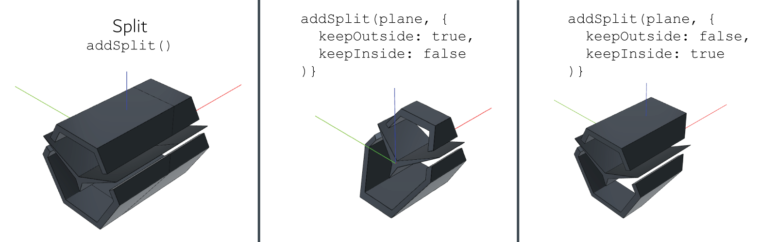
Inside and Outside is defined according to the direction of the normal of
splitPlane.
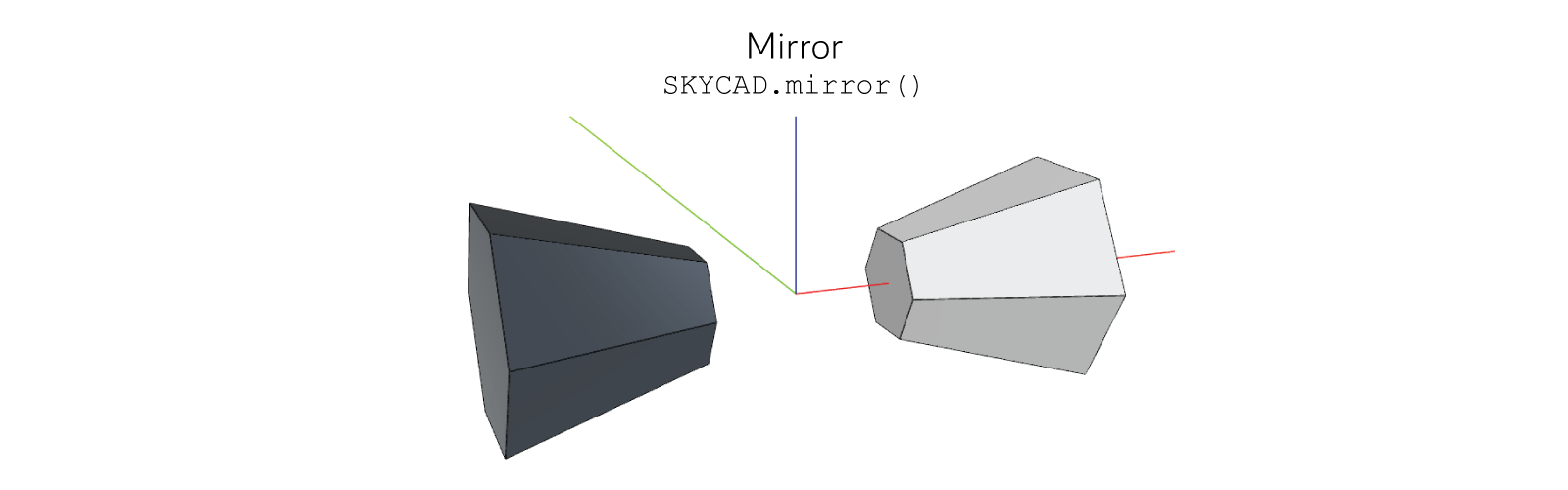
Mirror
const geometryGroup = new SKYCAD.GeometryGroup()

const originalModel = GEOM3D.generateModel()
geometryGroup.addGeometry(originalModel, {
  materials: [new SKYCAD.Material({ color: 0xcccccc })],
})

const mirroredModel = SKYCAD.mirror(originalModel, new SKYCAD.Plane(1, 0, 0, 0))
geometryGroup.addGeometry(mirroredModel, {
  materials: [new SKYCAD.Material({ color: 0x424a52 })],
})
Not only models can be mirrored in any direction, but entire geometries (containing even layouts), planes and connectors
too. Only text added to layouts (including those from dimensions) get mirrored only in position, but not the
letters/numbers so that they are readable when applying SKYCAD.mirror(). Some of these examples:
const xPlane = new SKYCAD.Plane(1, 0, 0, 0)

// Vectors
const vector3D = new SKYMATH.Vector3D(1, 1, 1)
const mirroredVector3D = SKYCAD.mirror(vector3D, xPlane) // returns SKYMATH.Vector3D(-1, 1, 1)

// Planes
const plane = new SKYCAD.Plane(1, 0, 1, 100)
const mirroredPlane = SKYCAD.mirror(plane, xPlane) // returns SKYCAD.Plane(-1, 0, 1, 100)

// Connectors
const connector3D = new SKYCAD.Connector3D({
  position: new SKYMATH.Vector3D(1, 1, 1),
  rotation: new SKYMATH.Vector3D(Math.PI / 4, 0, Math.PI / 2),
})
const mirroredConnector3D = SKYCAD.mirror(connector3D, xPlane) // returns SKYCAD.Connector3D({ position: new SKYMATH.Vector3D(-1, 1, 1), rotation: new SKYMATH.Vector3D(Math.PI / 4, 0, -Math.PI / 2) })

const geometryGroup = GEOM3D.generateHouseModuleGeometry() // can include layouts with dimensions, text, etc
const mirroredGeometryGroup = SKYCAD.mirror(geometryGroup, xPlane)
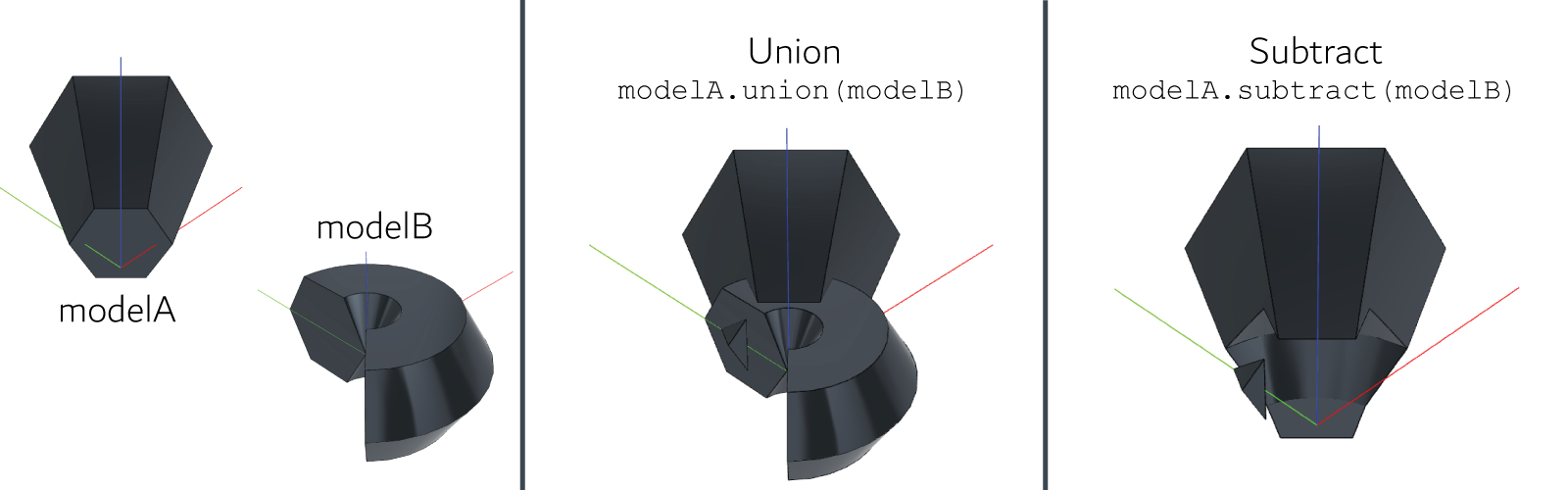
Union
modelA.union(modelB) // adds modelB to modelA, modifying modelA
Subtract
modelA.subtract(modelB) // removes modelB from modelA, modifying modelA
Name
Typically, when exporting geometry as BIM or STEP format, names in models are useful to identify every model involved in a geometry with different models. You can assign a name to a model by doing the following:
const model = new SKYCAD.ParametricModel({ name: 'Cube ' })

// or
const model = new SKYCAD.ParametricModel()
model.name = 'Cube'
Mesh Model
A mesh model is a collection of vertices, edges and faces that defines the shape of a polyhedral object of an imported file (e.g. stl).
Like a parametric model it lacks the information about its material or position. However, a mesh model also lacks bounds when imported. You can add them when creating the mesh model if you know them or use an open source stl viewer to retrieve them automatically.
const meshModel = new SKYCAD.MeshModel(ASSETS.URLS.MY_STL, {
  bounds: new SKYCAD.Bounds3D(new SKYMATH.Vector3D(0, 0, 0), new SKYMATH.Vector3D(50, 20, 100)),
})
Having bounds in a mesh model is useful when updating the camera, for collision detection with other existing models, selection handling and more.
Notice that a URL is to be used for the model. Therefore this makes it useful when using external storage solutions or in combination with the DynaMaker plugin DAS.
Example - Bike Wheel
Here is a complete example that uses mesh models, together with materials and a container for the models called geometry group.
// Rim component geometry
generateGeometry() {
  const geometryGroup = new SKYCAD.GeometryGroup()
  const model = new SKYCAD.MeshModel(ASSESTS.URLS.RIM_STL)
  geometryGroup.addGeometry(model, { materials: [new SKYCAD.Material({ color: 0x333333 })] })
  return geometryGroup
}
// Tyre component geometry
generateGeometry() {
  const geometryGroup = new SKYCAD.GeometryGroup()
  const model = new SKYCAD.MeshModel(ASSESTS.URLS.TYRE_STL)
  geometryGroup.addGeometry(model, { materials: [new SKYCAD.Material({ color: 0xfbfbf0 })] })
  return geometryGroup
}
// Wheel component
export class WheelComponent {
  private componentHandler = new STUDIO.ComponentHandler()

  constructor() {
    this.componentHandler = new STUDIO.ComponentHandler()
    this.componentHandler.add(new RIM.Component())
    this.componentHandler.add(new TYRE.Component())
  }

  generateGeometry() {
    const geometryGroup = this.componentHandler.generateAllGeometry()
    return geometryGroup
  }
}
Instead of creating a mesh model like
const rimModel = new SKYCAD.MeshModel(ASSESTS.URLS.RIM_STL), you can also create a static model directly likeconst rimModel = ASSESTS.STATIC_MODELS.RIM_STL. The difference between both is that a static model includes the 3D bounds (useful e.g. for collision detection or camera centering), whereas a mesh model lacks this information and therefore must be defined in its definition as seen before. You can read more in this how-to example to see how to create static models efficiently.
Connector
A 3D connector is a point in the world with its own coordinate system. It can be defined by the position and rotation vectors.
const myConnector = new SKYCAD.Connector3D({
  position: new SKYMATH.Vector3D(50, 100, 0),
  rotation: new SKYMATH.Vector3D(Math.PI / 2, Math.PI / 4, 0),
})
Connectors can be used in different ways. However, check their most common use in this how-to example with a robotic arm.
Color
In DynaMaker it is possible to work with different color systems:
Hexadecimal
JavaScript/TypeScript can already handle hexadecimal colors, and so does DynaMaker.
Create a hexadecimal color by just adding 0x before the 6 digits/letters that define the color.
const hexColor = 0xffffff
If you try to
console.log()white as0xFFFFFFand you will see that it automatically returns the decimal color16777215. Also, notice that0xFFFFFF === 16777215returnstrueso both definitions (hexadecimal and decimal) can be used interchangeably without any problem. See other examples here.
You can convert a hexadecimal color to RGB (and use other functions) with:
const rgbColor = SKYCAD.parseColor(0xffffff) // returns SKYCAD.RgbColor
RGB
Create a RGB color with values from 0 to 255, with alpha to represent its opacity (from 0 to 1) as:
const rgbColor = new SKYCAD.RgbColor(0, 125, 255, { alpha: 0.2 }) // light blue
const clonedRgbColor = rgbColor.clone() // creates a copy
const isSameRgbColor = rgbColorA.equals(rgbColorB) // returns true if rgbColorA is rgbColorB, ignoring alpha
const alpha = rgbColor.getAlpha() // gets the value of alpha
const rgbArray = rgbColor.toRgbArray() // returns list of values from 0 to 255 as [R, G, B]
const cmykArray = rgbColor.toCmykArray() // returns list of values from 0 to 100 as [C, M, Y, K]
const hexadecimalColor = rgbColor.toRgbNumber() // returns a hexadecimal color
const hexadecimalColorString = rgbColor.toHexString() // returns a hexadecimal color as string with # before the 6 digits/letters (e.g. '#FFFFFF')
const isItemRgbColor = SKYCAD.isRgbColor(item) // returns true if item is SKYCAD.RgbColor
CMYK
Create a CMYK color with values from 0 to 100, with alpha to represent its opacity (from 0 to 1) as:
const cmykColor = new SKYCAD.CmykColor(100, 50, 0, 0, { alpha: 0.3 }) // light blue
const clonedCmykColor = cmykColor.clone() // creates a copy
const isSameCmykColor = cmykColorA.equals(cmykColorB) // returns true if cmykColorA is cmykColorB, ignoring alpha
const alpha = cmykColor.getAlpha() // gets the value of alpha
const cmykArray = cmykColor.toCmykArray() // returns list of values from 0 to 100 as [C, M, Y, K]
const hexadecimalColor = cmykColor.toRgbNumber() // returns a hexadecimal color
const hexadecimalColorString = cmykColor.toHexString() // returns a hexadecimal color as string with # before the 6 digits/letters (e.g. '#FFFFFF')
const isItemCmykColor = SKYCAD.isCmykColor(item) // returns true if item is SKYCAD.CmykColor
RAL
RAL colors are used mainly in the industry for varnish, powder coating and plastic. Since it is a color system difficult to produce, RAL colors in websites are close representations of their true color.
Create a RAL color as four digits given by the standard, with alpha to represent its
opacity (from 0 to 1) as:
const ralColor = new SKYCAD.RalColor(9005, { alpha: 0.3 }) // black
const clonedRalColor = ralColor.clone() // creates a copy
const isSameRalColor = ralColorA.equals(ralColorB) // returns true if ralColorA is ralColorB, ignoring alpha
const alpha = ralColor.getAlpha() // gets the value of alpha
const rgbArray = ralColor.toRgbArray() // returns list of values from 0 to 255 as [R, G, B]
const cmykArray = ralColor.toCmykArray() // returns list of values from 0 to 100 as [C, M, Y, K]
const hexadecimalColor = ralColor.toRgbNumber() // returns a hexadecimal color
const hexadecimalColorString = ralColor.toHexString() // returns a hexadecimal color as string with # before the 6 digits/letters (e.g. '#FFFFFF')
const isItemRalColor = SKYCAD.isRalColor(item) // returns true if item is SKYCAD.RalColor
const isItemRalColorCode = SKYCAD.isRalColorCode(item) // returns true if item is SKYCAD.RalColorCode
In DynaMaker, the main use of RAL colors is in the RAL color parameter, which always
operates in RAL colors (i.e. input and output as 4 digits). For example the RAL color Yellow orange can be represented
as 2000.
Notice that there's no direct translation from hexadecimal, RGB or CMYK to RAL, so if you need to switch between these color systems in DynaMaker, it's always better to create a constant or function in between that helps with the matching.
Any other purpose, like color in sketches, models, etc, the color used needs to follow the other mentioned color systems.
Material
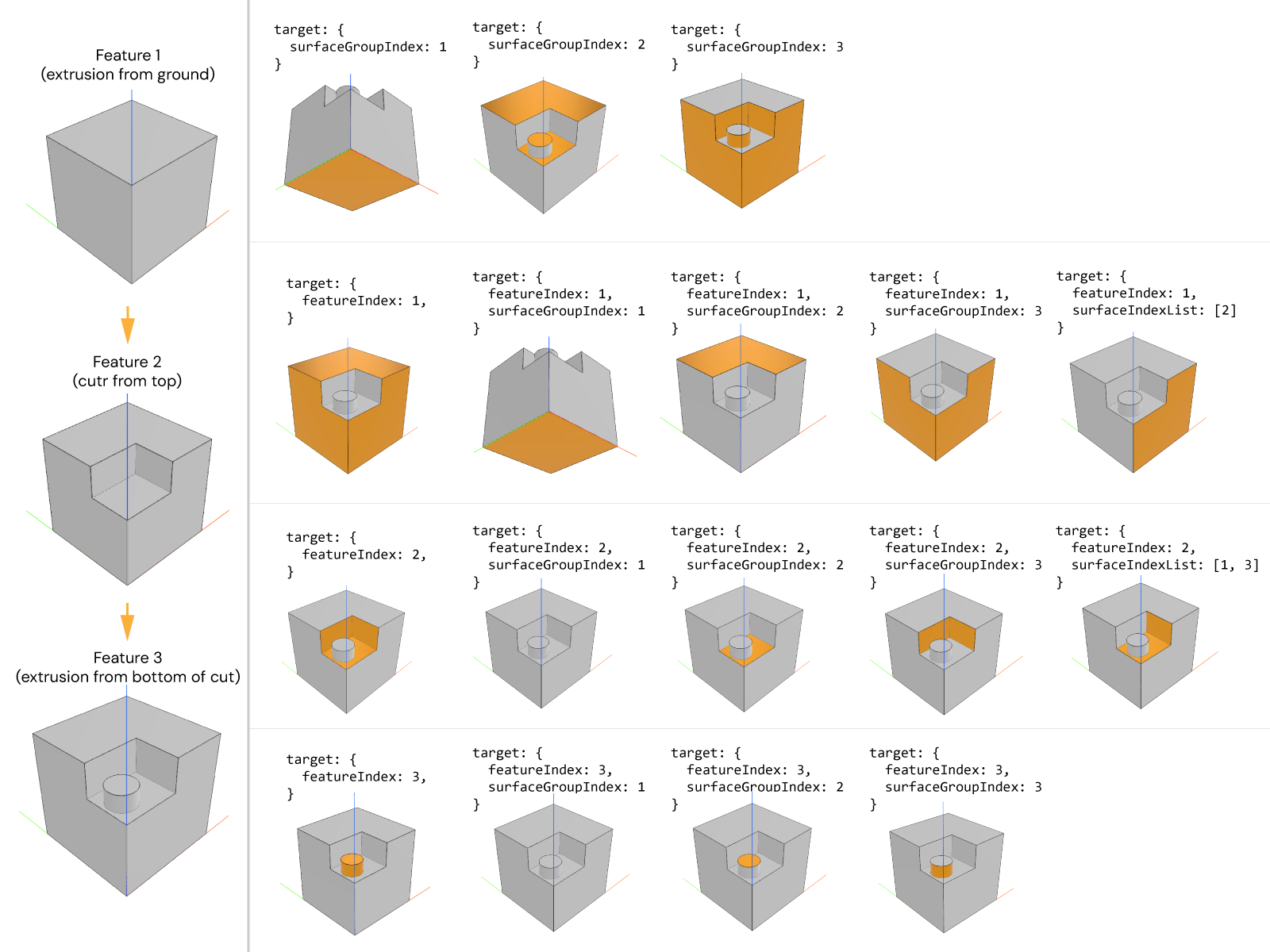
Materials are added to models when added to the geometry groups. Create a material by using some of the most common optional arguments:
coloras hexadecimal or RGB.opacityas a value from0(for transparent) to1(for opaque).metalnessas a value from0(for plastic) to1(for metal) to change how intensely the light is reflected in the surfaces.roughnessas a value from0(for smooth) to1(for rough) to change how smoothly the light is reflected in the surfaces.targetas an object with:featureIndexas number to apply the material to a specific CAD feature of the model, being1the first CAD feature,2the second CAD feature and so on.surfaceGroupIndexas number to apply the material to the model being start =1, end =2, side =3of the CAD feature to target specific surfaces in a group.surfaceIndexListas list of numbers to apply the material to a specific face of the model given the index of the face when the model is generated. It must be combined with at least one of the previoust two arguments.
Most common examples:
const material = new SKYCAD.Material({ color: 0x445464, opacity: 0.7 })
const materials = [material]
geometryGroup.addGeometry(myModel, { materials })

const steelMaterial = new SKYCAD.Material({ color: 0xcccccc, metalness: 0.5, roughness: 0.1 })
const metallicMaterials = [steelMaterial]
geometryGroup.addGeometry(mYmodel, { materials: metallicMaterials })

const baseMaterial = new SKYCAD.Material({ color: 0xff0000, target: { surfaceGroupIndex: 1 } })
const sideMaterial = new SKYCAD.Material({ color: 0xff0000, target: { surfaceGroupIndex: 3 } })
const topMaterial = new SKYCAD.Material({ color: 0xff0000, target: { surfaceGroupIndex: 2 } })
const multipleMaterials = [baseMaterial, sideMaterial, topMaterial]
geometryGroup.addGeometry(mYmodel, { materials: multipleMaterials })
Example with target and its combination of arguments:
With Textures
There are some extra optional arguments of a SKYCAD.Material that are meant for textures:
textureIdto refer to the texture from Files from the app dashboard.textureWidthto change the widthwise size of the texture.textureHeightto change the heightwise size of the texture.textureOffsetto move the texture with an offset (e.g. in case you want to match an edge with the model).textureRotationto rotate the texture with an angle (in radians).textureRotationCenterto set the point to rotate the texture around (asSKYMATH.Vector2D).
Most common example:
const materialsWithTextures = [new SKYCAD.Material({ textureId: ASSETS.TEXTURES.WOOD })]
Check the how-to example to how to add textures in detail.
Override named materials in GLB/GLTF models
You can customize any material in your GLB mesh model by simply specifying the material's name when creating your
SKYCAD.Material object. To demonstrate this, let's consider a GLB model of a chair that consists of two materials:
seat_material and frame_material. In a component, you could dynamically assign different colors to the seat and
frame of the chair using something like the following code:
const { seatColor, frameColor } = this.getProperties()

const geometryGroup = new SKYCAD.GeometryGroup()

geometryGroup.addGeometry(ASSETS.STATIC_MODELS.CHAIR, {
  materials: [
    new SKYCAD.Material({
      name: 'seat_material',
      color: seatColor,
    }),
    new SKYCAD.Material({
      name: 'frame_material',
      color: frameColor,
    }),
  ],
})
By creating instances of SKYCAD.Material and specifying the desired name and color, you can override the default
materials in your GLB model. This means you can easily apply different colors or textures to specific parts of the
chair, such as the seat and frame.
Geometry Group
Whenever you have multiple models that belong together, e.g. a door blade and its door handle, you can put them in the same GeometryGroup. You can then position, rotate and scale the group as one unit without having to fiddle with its internal structure.
const doorGeometryGroup = new SKYCAD.GeometryGroup()
doorGeometryGroup.addGeometry(doorBladeModel, {
  position: new SKYMATH.Vector3D(-100, 100, 0),
  rotation: new SKYMATH.Vector3D(Math.PI / 2, 0, 0),
  materials: [ new SKYCAD.Material({ color: 0x445464, opacity: 0.3 }) ]
  scale: 1
})
doorGeometryGroup.addGeometry(doorHandleModel, {
  position: new SKYMATH.Vector3D(0, 100, 0),
  materials: [ new SKYCAD.Material({ color: 0x25ADF3, opacity: 0 }) ]
})
Changing the position of
geometrymakes all its members follow the new position. This is ideal if you want to move subgroups of geometries. Eg.doorGeometryGroup, containing the door blade and handle models, could be withinhouseGeometryGroup.
2D Projections
2D projections are created via SKYCAD.project(), whose result is a layout. Given a plane,
create a projection as follows with these optional arguments:
excludeTagsas a list of strings to exclude all geometries and components with those tags for the projection (time-saving!)
const componentGeometry = component.generateGeometry()
const projectionLayout = SKYCAD.project(componentGeometry, plane), {
  excludeTags: ['screw', 'nuts'],
})
Remember that generating a projection depends heavily on what's to project. So the more complex geometries you have, the more time it will take for the algorithm to detect what it's behind and so on. Therefore if you are experiencing long loading times when doing projections you can:
- A. Reduce model complexity: keep sketches and models simple (avoid holes or curves when barely visible). If you need the 3D details for the app, it might be worthy to have 2 functions for generating geometry: one with details for the app, and another without them for the drawing.
- B. Remove what you don't need in your drawings by using
excludeTags(e.g. screws of 1cm in a 10m product might be irrelevant). Remember that removing models saves a lot of time since they are skipped completely.- C. Use sketches instead: if you already have sketches that represent perfectly your component, why would you need projections then? Although it might take time to implement, this alternative is way faster than a projection.
- D. Use pictures from the app instead of projections when a projection doesn't add any extra value, e.g. an isometric view with no dimensions. Read more here to see how to implement it.
Tags
Track the geometry group easier by using tags as:
geometryGroup.addTag('door') // tags the geometry with the string 'door'
const hasDoorTag = geometryGroup.hasTag('door') // returns true if geometryGroup has the given tag 'door'
const tags = geometryGroup.getTags() // returns a list of the tags as strings
Having tags in your geometry makes it easier if you want to skip certain parts of a model or geometry for a projection for example. Doing so, a projection will take significantly less time since it completely ignores that geometry for the calculation. Another way to add a tag for each subgeometry of a geometry group could be done as follows:
geometryGroup.addGeometry(doorModel, { tags: ['door'] })
geometryGroup.addGeometry(doorHandleModel, { tags: ['handle'] })
geometryGroup.addGeometry(doorHingesModel, { tags: ['hinge'] })
const projectionLayout = SKYCAD.project(geometryGroup, plane, { excludeTags: ['handle', 'hinge'] })
If you want to ignore a whole component for a projection, you don't need to tag all parts of it's geometry. It is enough with tagging the component when adding it to the component handler, so that the instance contains the tag. Of course, you can indistinctly combine tags in geometry and tags in components for projections. You can read more about tags in components here with other uses like removing or getting certain components.
Geometric Transformations
const scale = geometryGroup.getScale() // gets scale as number
const position = geometryGroup.getPosition() // gets position as SKYMATH.Vector3D
const rotation = geometryGroup.getRotation() // gets rotation as SKYMATH.Vector3D
geometryGroup.setPosition(new SKYMATH.Vector3D(1, 10, -7))
geometryGroup.setRotation(new SKYMATH.Vector3D(0, 0, Math.PI / 2))
geometryGroup.setScale(0.7)
The system used for rotation of geometries uses Euler angles, which is commonly used in the industry (e.g. cars, robotics, etc). This system applies the 3D vector of rotation in a specific order: first the x-coordinate, second the y-coordinate, and last the z-coordinate.
Try this interactive app that shows the Euler rotation which is the sum of all rotations for each coordinate in the aforementioned order:
Other
const clonedGeometryGroup = geometryGroup.clone() // creates a copy
const isGeometryEmpty = geometryGroup.isEmpty() // returns true if no models/geometry was added with addGeometry()
const geometries = geometryGroup.getGeometry() // returns a list of geometries and models added
Font
The default font used in the 3D scene and exported PDF drawings is Liberation Sans, which is included in SKYCAD. If you
want to use a different font, we recommend uploading the font file to the dashboard and referencing it through the
ASSETS namespace.
The font format must be
.ttfor.otf. Make sure said font doesn't contain faulty characters. Each version of a font (i.e. italic, bold, cursive, all caps, etc) is a different font and therefore all must be loaded separately. E.g. try norse.otf from FontSpace.
To use your custom font, you need to load it first. Notice that this has to be in an async function, and therefore can
only be done in the UI editor and then passed to the components or drawings where needed. Depending on the case to
change the font in:
-
whole app: in UI make
onInit()asynchronous, so that the font can be loaded and set as default afterwards:export async function onInit() {const { id: fontId } = await SKYCAD.loadFont(ASSETS.URLS.MY_FONT_TTF)SKYCAD.setDefaultFont(fontId)// rest of logic} -
specific (text in) layout of a drawing: in ACTIONS make the function that generates the drawing asynchronous, so that the
fontIdcan be passed as input to the drawing and used in a layout:// ACTIONSexport async function generateQuotationDrawing() {const { id: fontId } = await SKYCAD.loadFont(ASSETS.URLS.MY_FONT_TTF)const assemblyComponent = getAssemblyComponent()const drawing = DRAWINGEXPORT.generateDrawing(assemblyComponent, { fontId })return drawing}// DRAWINGexport function generateDrawing(assemblyComponent: CUBE.Component, { fontId = undefined } = {}) {// fontId as undefined = Liberation Sansconst layout = new SKYCAD.Layout({ defaultFontId: fontId }) // sets the font to the entire layoutlayout.addText('hello', { fontId }) // sets the font to specific text in layout// rest of logic} -
specific static (text in) layout of a component: in UI, make
onInit()asynchronous, so that thefontIdcan be passed as property to the new top-level component, and used within the component editor as any other property:// UIexport async function onInit() {const { id: fontId } = await SKYCAD.loadFont(ASSETS.URLS.MY_FONT_TTF)const newAssemblyComponent = new ASSEMBLY.Component()newAssemblyComponent.setProperties({ fontId })Studio.getComponentHandler().add(newAssemblyComponent)// rest of logic} -
specific dynamic (text in) layout of a component (e.g. changing language to cyrillic or greek alphabet by changing app language through button or configurator): in UI make the button or configurator callback asynchronous, so that the
fontIdcan be passed as property to the top-level component, and used within the component editor as any other property:const changeLanguageButton = new SKYUI.Button('Change language', async () => {const assemblyComponent = ACTIONS.getAssemblyComponent() // typical custom function that returns existing assembly componentconst { id: fontId } = await SKYCAD.loadFont(ASSETS.URLS.MY_FONT_TTF)assemblyComponent.setProperties({ fontId })Studio.requestGeometryUpdate()})const assemblyComponent = ACTIONS.getAssemblyComponent() // typical custom function that returns existing assembly componentconst configurator = ASSEMBLY.getConfigurator(assemblyComponent)configurator.addCompletionCallback(async (valid, values) => {const language = values['language-parameter-id']const fontTtf = getFontTtf(language) // custom function that returns the correct asset based on language (ASSETS.URLS.MY_FONT_TTF)const { id: fontId } = await SKYCAD.loadFont(fontTtf)assemblyComponent.setProperties({ fontId })Studio.requestGeometryUpdate()})
Here is an example of a component using
fontIdas property:
G-code
Geometric- or G-code is a CNC programming language that directs a CNC machine's functions related to the cutting tool's movement, combining instructions readable by the microcontroller without requiring intricate logic or math skills.
The syntax is usually defined as [Command]-[Parameter] and additional fields can be added depending on the command
type of tool settings. Knowing that a path is a group of movements that are determined by a start and a stop (equivalent
of sketch.moveTo()), in DynaMaker you can generate the G-code from a sketch with:
const gcodeList = SKYCAD.generateGcodeFromSketch(sketch, {
  prePathCommands: ['G0 X0 Y0'],
  postPathCommands: ['G0 X10 Y10'],
  resolution: 1000,
})
where you can set the resolution and pre- and post-commands as optional arguments of the tool path. Through this
function, each tool movement is registered as a command with certain parameters and would be the equivalent of
DynaMaker's own way of creating sketches through sketch.moveTo(), sketch.lineTo() and sketch.curveTo() to give
some examples.
The commands generated from this function are:
- G0: Rapid Linear Motion (i.e.
moveTo()) - G1: Linear Motion (i.e.
lineTo()) - G2: Arc motion clockwise (i.e.
curveTo({ clockwise: true })) - G3: Arc motion counterclockwise (i.e.
curveTo({ clockwise: false }))
and the parameters generated are:
- X: x-coordinate
- Y: y-coordinate
- I: Arc radius in x-axis
- J: Arc radius in y-axis
However these commands might be limited and you you might want to complete the result with your own tool movements and
settings. Since the result of this function is a list of instructions as string, other commands like change tool
height (Z), tool feed rate (F) or tool power settings (M5 to turn off) could be easily added given the index in the
list:
gcodeList.splice(index, 0, 'M5')to insert new instructiongcodeList[index] = 'M5'to replace an instructiongcodeList[index].push(' F1000')to add additional in-line instructionsgcodeList.splice(index, 1)to remove an instruction
Click here to see an example of G-code generated with SKYCAD.generateGcodeFromSketch():
gcodeList = [
  'G0 X4.282623 Y-3.602849',
  'G0 X0 Y0',
  'G1 X0.337272 Y-1.887587',
  'G1 X3.937250 Y-3.997522',
  'G2 X3.981299 Y-4.051420 I-0.050565 J-0.086274',
  'G1 X4.317355 Y-5.033493',
  'G1 X4.663541 Y-4.050827',
  'G2 X4.707295 Y-3.997781 I0.094318 J-0.033228',
  'G1 X8.307715 Y-1.887587',
  'G1 X4.362364 Y-3.602849',
  'G2 X4.282623 Y-3.602849 I-0.039871 J0.091708',
  'G0 X10 Y10',
  'G0 X7.971612 Y-2.799547',
  'G0 X0 Y0',
  'G1 X7.640654 Y-3.044232',
  'G1 X8.015510 Y-3.693521',
  'G2 X8.015509 Y-3.793521 I-0.086603 J-0.049999',
  'G1 X6.183422 Y-6.966731',
  'G1 X2.519269 Y-6.966731',
  'G2 X2.432667 Y-6.916732 I0.000000 J0.100000',
  'G1 X0.600580 Y-3.743522',
  'G1 X0.986443 Y-3.075177',
  'G3 X0.960986 Y-2.946049 I-0.086603 J0.049999',
  'G1 X0.614770 Y-2.678513',
  'G1 X0.028753 Y-3.693521',
  'G3 X0.028753 Y-3.793522 I0.086602 J-0.050000',
  'G1 X2.161209 Y-7.486962',
  'G1 X6.426036 Y-7.486962',
  'G3 X6.512638 Y-7.436963 I0.000000 J0.100000',
  'G1 X8.645115 Y-3.743522',
  'G1 X8.117664 Y-2.829957',
  'G3 X8.051446 Y-2.782056 I-0.086602 J-0.050000',
  'G3 X7.971612 Y-2.799547 I-0.020384 J-0.097900',
  'G0 X10 Y10',
  'G0 X2.432667 Y-0.570268',
  'G0 X0 Y0',
  'G1 X1.674503 Y-1.883428',
  'G1 X1.302877 Y-1.699491',
  'G2 X1.251521 Y-1.638827 I0.044359 J0.089623',
  'G2 X1.260633 Y-1.559868 I0.095715 J0.028959',
  'G1 X2.161209 Y-0.000038',
  'G1 X6.426035 Y-0.000038',
  'G2 X6.512637 Y-0.050037 I-0.000000 J-0.100000',
  'G1 X7.391768 Y-1.572724',
  'G1 X6.976275 Y-1.726992',
  'G2 X6.854865 Y-1.683245 I-0.034807 J0.093747',
  'G1 X6.183422 Y-0.520269',
  'G1 X2.519269 Y-0.520269',
  'G3 X2.432667 Y-0.570268 I-0.000000 J-0.100000',
  'G0 X10 Y10',
]