My First Component
In this tutorial, you will learn more in depth how to modify the geometry of a component so that it follows its configurable size. It also covers the basics of presets, refactoring & debugging. As a product example, we will use a configurable flat metal bracket with some holes.
For this we will follow 5 simple steps:
Don't forget to check the common mistakes if you get stuck. Good luck!
1. Create App
As done in My First App:
- Create a new app and name it for example Bracket App.
- Create a new component called e.g. Bracket.
Skip the connection between the app and the component, since this tutorial focuses on the component and its geometry.
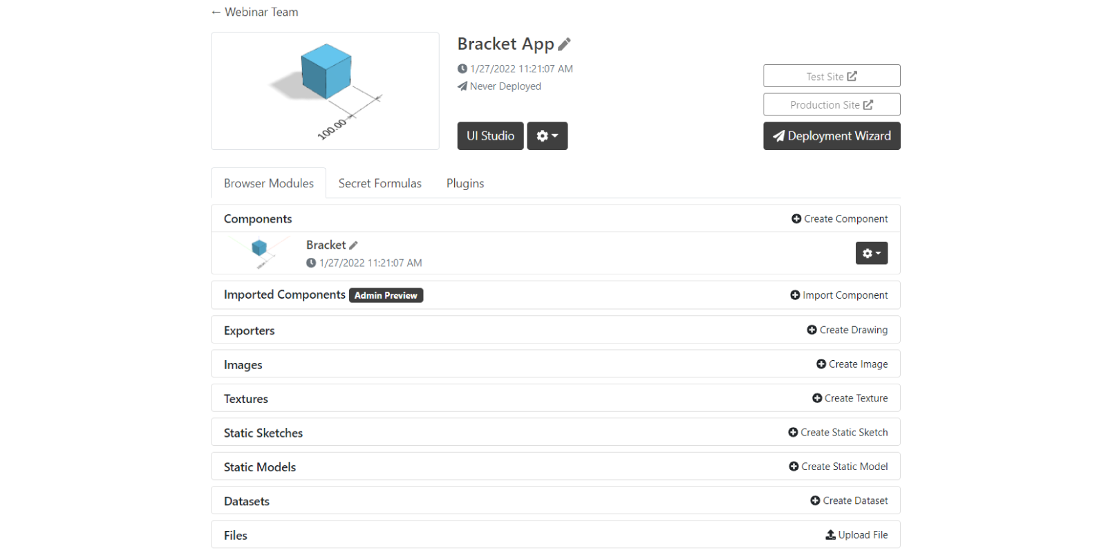
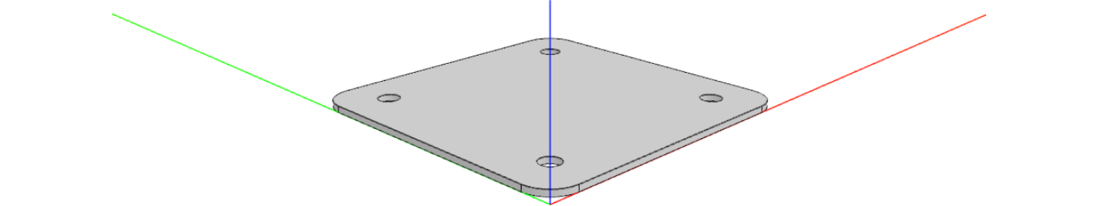
Understanding how the component is structured is the key to create your app in the best way possible. When you go into a component (by clicking the thumbnail or its name Bracket), you can see the code (right) that generates the preview (left):

On the right side of the code (right), you can find the following tabs:
- BRACKET - This will have the name that your gave your component and it is the entry point when some other component or the UI uses it.
- PARAMETERS - To generate configurators with parameters that can modify the component.
- COMPONENTS - To define the structure and logic of the component.
- GEOM3D - To define the 3D geometry of the component.
- GEOM2D - To define the 2D geometry of the component.
- CONSTANTS - To store all your constants.
Above the preview on the left, you can find a button to create new tests. The tests use your code on the right hand side to create the preview on the left. Next to the button is a dropdown where you can select which test to run or edit.
2. Modify Model
We will modify the model in 5 different steps:
- A. Change the cube to a flat sheet
- B. Add a set of holes intended for rivets and bolts
- C. Round the corners of the sheet
- D. Change the color
- E. Create configurator
A. Flat sheet
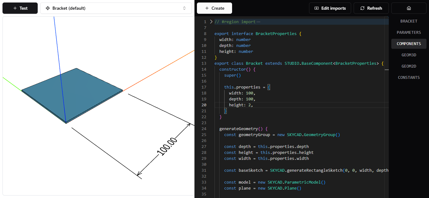
Start with creating a new component with the + Create button. To change the height of the cube, we need to update its default property value.
- In COMPONENTS, notice that in the
constructorwe have the propertieswidth,depth&height. - Change the default value of
heightfrom100to2:
constructor() {
  super()

  this.properties = {
    width: 100,
    depth: 100,
    height: 2,
  }
}
- Save to apply changes.
B. Holes
Let's add some holes that dynamically appear or disappear depending on the size of the sheet. For now, let's add one in the middle.
-
In COMPONENTS, notice that
generateGeometry()is creating an extrusion asmodel.addExtrude() -
Use the existing model to add the extrude cut afterwards with the proper arguments:
holeSketchas the sketch to define the shape of the cut.planeas the plane from where the cut is done (on the ground by default, same for extrusion).heightfor the length of the cut.
generateGeometry() {
  // properties

  const model = new SKYCAD.ParametricModel()
  const baseSketch = SKYCAD.generateRectangleSketch(0, 0, width, depth)
  const plane = new SKYCAD.Plane()
  model.addExtrude(baseSketch, plane, height)

  const holeSketch = SKYCAD.generateCircleSketch(width / 2, depth / 2, 7) // position = (width / 2, depth / 2); diameter = 7
  model.addExtrudeCut(holeSketch, plane, height)

  // color & material

  const geometryGroup = new SKYCAD.GeometryGroup()
  geometryGroup.addGeometry(model, { materials })

  // layout with dimension

  return geometryGroup
} -
Save to save the changes and update the model with the hole.
Perfect! We will repeat this process for more holes in the rest of the corners, but we will add some rules so the holes don't collide with each other for example. As an example you can have the following:
generateGeometry() {
  // properties

  // Extrusion
  const model = new SKYCAD.ParametricModel()
  const baseSketch = SKYCAD.generateRectangleSketch(0, 0, width, depth)
  const plane = new SKYCAD.Plane()
  model.addExtrude(baseSketch, plane, height)

  // Holes
  const MARGIN = 15

  if (width <= 50 && depth <= 50) {
    const holeSketch1 = SKYCAD.generateCircleSketch(width / 2, depth / 2, 7)
    model.addExtrudeCut(holeSketch1, plane, height)
  } else if (width > 50 && depth <= 50) {
    const holeSketch1 = SKYCAD.generateCircleSketch(MARGIN, depth / 2, 7)
    const holeSketch2 = SKYCAD.generateCircleSketch(width - MARGIN, depth / 2, 7)
    model.addExtrudeCut(holeSketch1, plane, height)
    model.addExtrudeCut(holeSketch2, plane, height)
  } else if (width <= 50 && depth > 50) {
    const holeSketch1 = SKYCAD.generateCircleSketch(width / 2, MARGIN, 7)
    const holeSketch2 = SKYCAD.generateCircleSketch(width / 2, depth - MARGIN, 7)
    model.addExtrudeCut(holeSketch1, plane, height)
    model.addExtrudeCut(holeSketch2, plane, height)
  } else {
    const holeSketch1 = SKYCAD.generateCircleSketch(MARGIN, MARGIN, 7)
    const holeSketch2 = SKYCAD.generateCircleSketch(width - MARGIN, MARGIN, 7)
    const holeSketch3 = SKYCAD.generateCircleSketch(MARGIN, depth - MARGIN, 7)
    const holeSketch4 = SKYCAD.generateCircleSketch(width - MARGIN, depth - MARGIN, 7)
    model.addExtrudeCut(holeSketch1, plane, height)
    model.addExtrudeCut(holeSketch2, plane, height)
    model.addExtrudeCut(holeSketch3, plane, height)
    model.addExtrudeCut(holeSketch4, plane, height)
  }

  // color & materials

  const geometryGroup = new SKYCAD.GeometryGroup()
  geometryGroup.addGeometry(model, { materials })

  // layout with dimension

  return geometryGroup
}
- Save to see the dynamic holes in each corner.
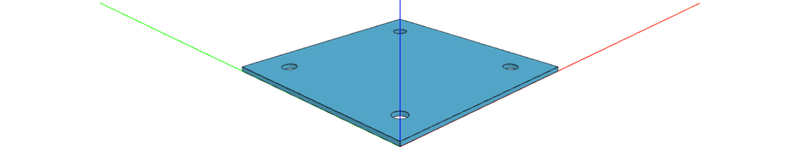
Try different values for the parameters width and depth and see how the holes behave when having values lower and
higher than 50 in this case.
C. Fillet
As a third step, we can also round the corners. For that we can simply add fillets for each node of baseSketch.
generateGeometry() {
  // properties

  // Extrusion
    const CORNER_RADIUS = 10
    const baseSketch = SKYCAD.generateRectangleSketch(0, 0, width, depth)
    baseSketch.getNodes().forEach((node, nodeId) => {
      baseSketch.addFillet(CORNER_RADIUS, nodeId)
    })

    const model = new SKYCAD.ParametricModel()
    const plane = new SKYCAD.Plane()
    model.addExtrude(baseSketch, plane, height)

  // holes

  // color & materials

  const geometryGroup = new SKYCAD.GeometryGroup()
  geometryGroup.addGeometry(model, { materials })

  // layout with dimension

  return geometryGroup
}
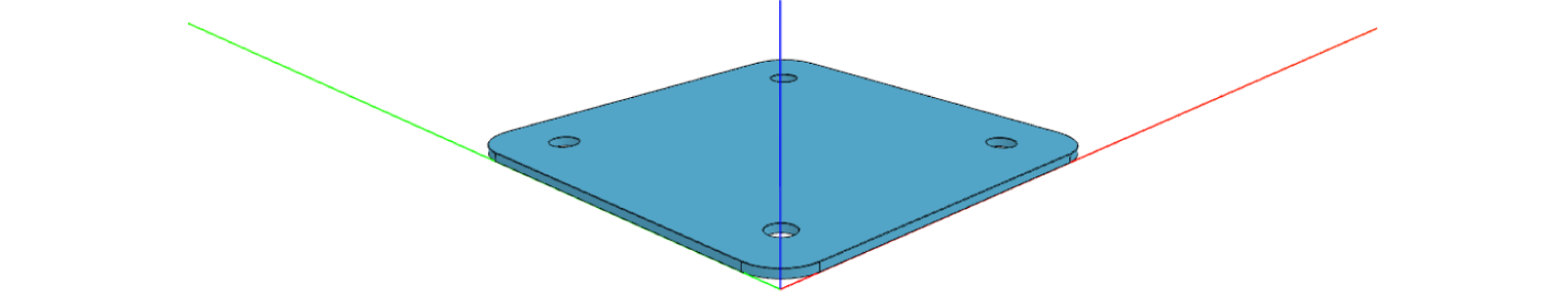
- Save to see the rounded corners.
D. Color
Changing the color of the component is very easy and has to be changed when adding the
model to a geometry group, which contains
information about the position, rotation and materials.
- In COMPONENTS, go to
generateGeometry(). - See that the model is added to the geometry group with
materials, which contains thecolor. - Similarly as done in My First App, set it to gray as:
const color = new SKYCAD.RgbColor(200, 200, 200) - Save to see the new color.
E. Create Configurator
Last but not least, we will create a configurator that can change the properties of our Bracket component. Above the
code, click the + Create button and select Configurator. Accept the defaults by clicking Create
Configurator. You automatically end up in the PARAMETERS tab where you can see the new
generateConfigurator() function.
Update the function to look like below. Don't worry if you don't understand the code at this point, you will learn more about it at a later stage. For now it's fine to copy and paste it.
export function generateConfigurator(component: COMPONENTS.Bracket): SKYPARAM.Configurator {
  const { width, depth, height } = component.getProperties()

  const widthParameter = SKYPARAM.generateSlider('width', 'Width (x)', {
    defaultValue: width,
    maxValue: 300,
    minValue: 20,
    stepSize: 0.1,
    unit: 'mm',
  })

  const depthParameter = SKYPARAM.generateInputParameter('depth', 'Depth (y)', {
    defaultValue: depth,
    maxValue: 300,
    minValue: 20,
    stepSize: 10,
    unit: 'mm',
  })

  const heightParameter = SKYPARAM.generateDropdown(
    'height',
    'Height (z)',
    [new SKYPARAM.DropdownItem('0.7', 0.7), new SKYPARAM.DropdownItem('2', 2), new SKYPARAM.DropdownItem('5', 5)],
    { defaultValue: height, unit: 'mm' },
  )

  const configurator = new SKYPARAM.Configurator([widthParameter, depthParameter, heightParameter])

  configurator.addCompletionCallback((valid, values) => {
    if (valid) {
      component.setProperties(values)
    }
  })

  return configurator
}
- Save to apply changes to the configurator.

3. Tests
Once you have the configurator set up, you might wonder: would I need to play with the parameters to see all the edge
cases? In DynaMaker is possible to create pre-defined versions (i.e. with different property values) of your component
as pure visualization tests. These allow us to try different values of the parameters (Width (x), Depth (y) &
Height (z)) within the component without going to the UI or any other component. The advantage of this is that you can
immediately see how the parameters affect your new features, e.g. the distribution of holes in this case. And most
importantly, these tests are saved! Let's put these words into action. For example, to see what happens with the
distribution of holes near the breakpoint width = 50 we will create two tests.
-
Still in the component Bracket, click + Test and select Component Test.
-
In the dropdown, select the component that you want to test, Bracket in our example, and click Next.
-
In the test editor, set the properties that you want to see.
export default function (): BRACKET.Bracket {
  const component = new BRACKET.Bracket()
  component.setProperties({
    width: 50,
    depth: 150,
    height: 0.7,
  })
  return component
} -
Give the test a name, e.g. Bracket (50x150x0.7) and click Save.
-
Create another test in the same way, but use
width: 51instead. -
Switch between the test in the dropdown above the Preview to see the difference.
-
Keep adding more presets until you covered all the edge cases, e.g. in this case:
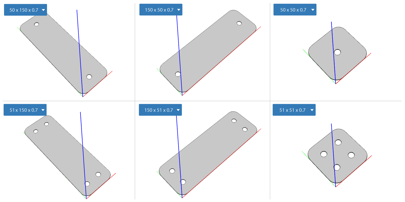
4. Refactoring
Cleaning the code or refactoring is quite important to make clear what you do in your components. Remember that you might not be the only one working on the project, so whatever you write has to be clear for anyone jumping into your project at any stage.
Imagine that someone wrote a function that does a lot of complex calculations. It works perfectly until 1 month later when a new feature is requested. Then the calculations must be changed and some things are wrong or simply not useful anymore. And add the extra difficulty when the developer that has to fix it is you and not the person that wrote it initially.
So as a first recommendation, keep things where they should be. In this case, you have might have noticed that
generateGeometry() starts to feel messy, and it's because it does too many things. As a general rule, if you break a
function into subfunctions with a specific logic, then it might be easier to read.
In this case we create both the models and sketches in COMPONENTS (within generateGeometry()), but we could
move the models to GEOM3D and the sketches and layouts to GEOM2D, so like:
// GEOM2D
export function generateBaseSketch(width: number, depth: number) {
  const CORNER_RADIUS = 10
  const baseSketch = SKYCAD.generateRectangleSketch(0, 0, width, depth)
  baseSketch.getNodes().forEach((node, nodeId) => {
    baseSketch.addFillet(CORNER_RADIUS, nodeId)
  })
  return baseSketch
}

export function generateHoleSketch(posX: number, posY: number) {
  const HOLE_DIAMETER = 7
  const holeSketch = SKYCAD.generateCircleSketch(posX, posY, HOLE_DIAMETER)
  return holeSketch
}

export function generateDimensionLayout(width: number) {
  const layout = new SKYCAD.Layout()

  const start = new SKYMATH.Vector2D(width, 0)
  const end = new SKYMATH.Vector2D(0, 0)
  layout.addDimension(start, end, { offset: 20, decimals: 1 })

  return layout
}
// GEOM3D
export function generateModel(width: number, depth: number, height: number) {
  const model = new SKYCAD.ParametricModel()
  const plane = new SKYCAD.Plane()
  const baseSketch = GEOM2D.generateBaseSketch(width, depth)
  model.addExtrude(baseSketch, plane, height)

  const MARGIN = 15

  if (width <= 50 && depth <= 50) {
    const holeSketch1 = SKYCAD.generateCircleSketch(width / 2, depth / 2, 7)
    model.addExtrudeCut(holeSketch1, plane, height)
  } else if (width > 50 && depth <= 50) {
    // and so on with the rest of the holes
  }

  return model
}
Remember to
exportthe functions in GEOM2D and GEOM3D that you want to use elsewhere, or you won't be able to use them in e.g. COMPONENTS. Also, the code completion should help you notice that.
Then once we've cleaned up the geometry-generators functions, we can clean generateGeometry(), e.g. like:
// COMPONENT
generateGeometry() {
  const { width, depth, height } = this.getProperties()

  const geometryGroup = new SKYCAD.GeometryGroup()
  const model = GEOM3D.generateModel(width, depth, height)
  geometryGroup.addGeometry(model, {
    materials: [new SKYCAD.Material({ color: new SKYCAD.RgbColor(200, 200, 200) })]
  })

  const layout = GEOM2D.generateDimensionLayout(width)
  geometryGroup.addGeometry(layout)

  return geometryGroup
}
See that the functions are not only much easier to read, but also ready for future reusability!
And as a second recommendation, keep things with a proper name, so when you read it you know what it does. In this
case in GEOM3D, having 50 everywhere is bad because you might wonder later what does this 50 mean? For
that, you should keep these numbers in variables or const. And also, as soon as you use something twice, try to move
it to a common place, like CONSTANTS. For example:
// CONSTANTS
export const HOLE_DIAMETER = 7
export const SIZE_LIMIT_FOR_HOLES = 50
Having these, we can update some values that we wrote in previous functions:
// GEOM2D
export function generateHoleSketch(posX: number, posY: number) {
  const holeSketch = SKYCAD.generateCircleSketch(posX, posY, CONSTANTS.HOLE_DIAMETER)
  return holeSketch
}
// GEOM3D
// [...]
if (width <= CONSTANTS.SIZE_LIMIT_FOR_HOLES && depth <= CONSTANTS.SIZE_LIMIT_FOR_HOLES) {
  const holeSketch = GEOM2D.generateHoleSketch(width / 2, depth / 2)
  model.addExtrudeCut(holeSketch, topPlane, -height)
} else if (width > CONSTANTS.SIZE_LIMIT_FOR_HOLES && depth <= CONSTANTS.SIZE_LIMIT_FOR_HOLES) {
// [...]
5. Debugging
When something is wrong in your component and you don't know exactly where the problem comes from, it's time to step into the code and check what's happening at specific points, also known as debugging.
Let's show a typical problem that can be fixed in 1 line of code. Taking the component we have made as an example, we have recreated the app and introduced an intentioned bug. Knowing that the UI has been modified to make it easier, are you able to find the width and depth that causes a bug with one of the holes in this app?
Show solution:
Exactly, when width < 50 and depth < 50 the hole gets misplaced.

Since it's related to geometry, what you would do is:
- Go to your component (i.e. Bracket).
- Create a new test with the values you found the bug with (e.g.
width: 20anddepth: 30). - Save and make that the new test is active.
Now you would see the problem clearly with those values. Let's start debugging:
- Still in your component, go to GEOM3D.
- Open the browser console (F12)
- Type
debuggerright before you want to start debugging. - Save to apply the change. Notice that it stops exactly at the line you typed debugger.
- By pressing F10 you can go on with the debugging line by line.
In this case, we find that we have swapped depth & width in line 16, so the correct code should have been:
const holeSketch = GEOM2D.generateHoleSketch(width / 2, depth / 2)

// instead of
// const holeSketch = GEOM2D.generateHoleSketch(depth / 2, width / 2)
If you are getting other sort of errors (e.g. component crashes), you can read more about debugging here.
Congratulations! You have finished the second tutorial. Having the component in an app would look like this:
Do you want to have a copy of this app in your team? Let us know at support@dynamaker.com! Remember that everyone has their own way of developing and there are multiple valid ways to do things as long as anyone can understand the code!
Now that you know how to create components, let's create an assembly with multiple components in the next tutorial My First Assembly.