My First Drawing
This page has not yet been updated to show the new component editor. Read about the changes here.
Let's create your first drawing in DynaMaker!
In this tutorial, you will learn how to create and autogenerate drawings. As a product example, we will reuse the staircase from My First Assembly.
For this we will follow 5 steps:
Don't forget to check the common mistakes if you get stuck. Good luck!
In the previous tutorial, we worked just with components by using the Component Editor. For the drawings we will do something similar but with its own editor or Drawing Editor.
1. Set Up Drawing Editor
When you create a new project, you will find there is a section for creating drawing in Exporters, right below your components. If you create a new one (named e.g. DrawingTemplate) and open it you will see the Drawing Editor, a tool for creating custom drawings.
A. Drawing Editor Basics
Why using Drawing Editor? It provides several advantages compared to regular drawings from other known CAD software solutions:
- Using the same template for different components.
- Using the same template for different purposes with minor changes. For example:
- DXF for laser cutting with scale 1 : 1.
- PDF including dimensions for quotations with different scales and views.
- Customizing drawing format and content depending on the component properties.
- Testing your drawing with presets allows you to try specific values of the component properties without making changes in the app/component.
- Testing is simple: just two buttons to download the drawing as PDF or DXF, and a third to switch between presets.
- Creating multiple templates with same core content but with certain differences. Typically a drawing intended for the customer could have limited content compared to a manufacturing drawing.
- And others like:
- Having multiple pages with different content.
- Adding tables automatically (BOM list, header, etc.) with combined cells.
- Changing color/style/scale of the content as desired.
This said, let's jump into it, but first we need to make sure we use the correct component.
B. Use Correct Component
In your new DrawingTemplate, you'll notice that under the DRAWING tab, only one function is exported:
generateDrawing(), which uses a geometry as input. By default, in the PRESETS tab, the geometry is set to a
cube. Using geometry as input keeps things simple since the function doesn't depend on a component. However, components
are often used because they provide additional functionality. Therefore, we'll use the component we need, which in this
case is Assembly, and for this we need to import it as if it's a subcomponent of the drawing:
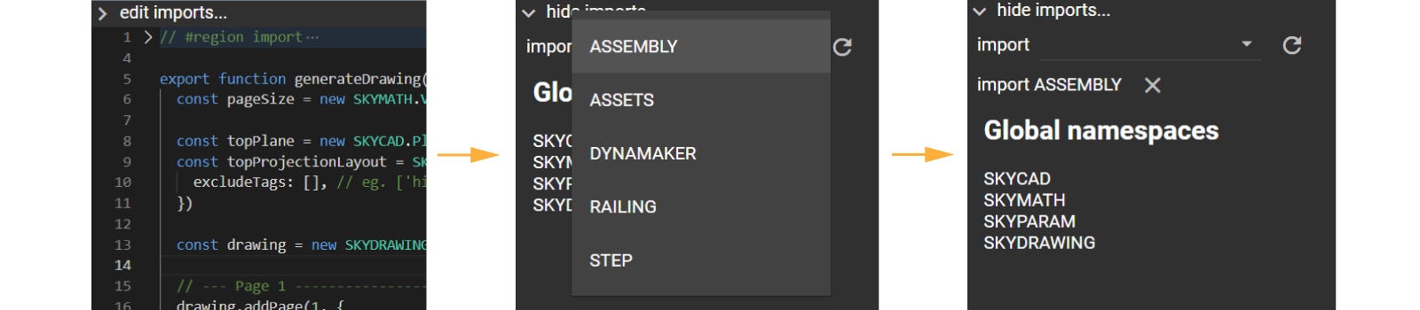
- In edit/hide imports... above the code editor, add Assembly from the imports dropdown. See how the
#region importupdates automatically.
If you want to leave a geometry as input for generateDrawing(), you could have the following in PRESETS
export const drawingPreset = new PRESET.PresetDrawing(DRAWING.generateDrawing)

const assemblyComponentA = new ASSEMBLY.Component()
drawingPreset.addCase([assemblyComponentA.generateGeometry()], { label: 'Default' })

const assemblyComponentB = new ASSEMBLY.Component()
assemblyComponentB.setProperties({ width: 2500, depth: 500, height: 3000 })
drawingPreset.addCase([assemblyComponentB.generateGeometry()], { label: 'W: 2500, D: 500, H: 3000' })
However, if you want to get more information from the component (e.g. size for dimensions, BOM list for a table, etc), it's best to send the component you want to make a drawing of as input. Since we need the component later in this tutorial, we will switch the input from geometry to Assembly component.
-
In DRAWING, make sure you have
assemblyComponentas input and create the geometry out of it, since it's used for the default projections in the drawing template.export function generateDrawing(assemblyComponent: ASSEMBLY.Component) {
const geometry = assemblyComponent.generateGeometry()
// rest of logic
} -
In PRESETS, make sure to have some presets that cover the edge cases. As examples:
export const drawingPreset = new PRESET.PresetDrawing(DRAWING.generateDrawing)

const assemblyComponentA = new ASSEMBLY.Component()
drawingPreset.addCase([assemblyComponentA], { label: 'Default' })

const assemblyComponentB = new ASSEMBLY.Component()
assemblyComponentB.setProperties({ width: 2500, depth: 500, height: 3000 })
drawingPreset.addCase([assemblyComponentB], { label: 'W: 2500, D: 500, H: 3000' }) -
Keep adding more cases until you think you have covered the edge cases (e.g. smallest & biggest staircase possible, a wide but short one, a narrow but high one, etc)
-
Save & Update (Ctrl+S) to finally see the drawing with the chosen preset.
-
Try going through your presets and download the drawing as it as 📥 PDF and 📥 DXF. For the latter, you can try any available free online DXF viewer.

Great! We will polish and keep adding more details to the drawing, like:
- adjusting the views or projections position, including dimensions and a third ISO view.
- adding logo & new cells to the header
- adding a bill of materials (BOM) as a table at the top-right corner, with some extra info.
- changing the drawing content depending on the file format.
2. Projections
See that the default views need to be refined: they need more space in between, more dimensions and probably some extra space to make sure it does not collide with the header and the later BOM table. Also, we will change the position of the view so it follows the European standard for technical drawings (ISO, first angle projection) and we will add a third projection as an isometric view.
A. Adjust Position
Let's say we want two projections for the following front and side views:

In order to put these projections in the drawing we will go through what's on the default drawing template first:
- A drawing can contain multiple pages with different size and content. In the template, only 1 page is added.
- A page can be added to a drawing through
drawing.addPage(pageNr). In here, thepageSizeis specified. - Content (as
SKYCAD.Layout) can be added to a drawing asdrawing.addContent(pageNr, contentLayout). In here, thetopProjectionLayoutis added. - Projections (as
SKYCAD.Layout) can be done throughSKYCAD.project(geometry, plane). - Headers (as
SKYCAD.Layout) can be added to a drawing in the same way, butdrawing.setHeader(pageNr, headerLayout). - Multiple contents and headers in any format can be added as desired to a drawing.
You will see additional optional arguments throughout these functions in the template that help polishing the style of the drawing. For now, we will remove the top view, and replace it with the front and side views.
Before seeing the solution below, you can try to implement these ideas yourself based on what you find in the template and by looking briefly at the library SKYDRAWING. In the end, you should end up having something similar to the following:
export function generateDrawing(assemblyComponent: ASSEMBLY.Component) {
  const { width } = assemblyComponent.getProperties()
  const geometry = assemblyComponent.generateGeometry()

  // Drawing
  const drawing = new SKYDRAWING.Drawing()
  const pageSize = new SKYMATH.Vector2D(297, 210)
  const margin = 10

  // Page 1
  let pageNr = 1
  drawing.addPage(pageNr, {
    pageHeight: pageSize.y,
    pageWidth: pageSize.x,
    margin,
  })

  // Content
  const contentLayout = new SKYCAD.Layout({ defaultDimensionExtensionLineType: 'extended' })

  // --- front view
  const frontPlane = new SKYCAD.Plane(-1, 0, 0, 2000) // offset of 2000 should be enough not to collide with the geometry
  const frontProjectionLayout = SKYCAD.project(geometry, frontPlane)
  contentLayout.addLayout(frontProjectionLayout)

  // --- side view
  const sidePlane = new SKYCAD.Plane(0, 1, 0, 2000)
  const sideProjectionLayout = SKYCAD.project(geometry, sidePlane)
  contentLayout.addLayout(sideProjectionLayout, {
    position: new SKYMATH.Vector2D(width + 500, 0),
  })

  // --- content in drawing
  const contentBounds = new SKYCAD.Bounds2D( // adjusted so that it doesn't collide with the header
    new SKYMATH.Vector2D(margin, margin),
    new SKYMATH.Vector2D(0.65 * pageSize.x, pageSize.y - 3 * margin),
  )

  const validScales = [1]
  for (let i = 0; i < 300; i++) validScales.push(1 / i)

  const { scaleLabel } = drawing.addContent(pageNr, contentLayout, {
    textSize: 3, // sets all text presented in the drawing to real size 3
    fitInside: {
      bounds: contentBounds,
      validScales,
    },
    align: {
      horizontal: 'center',
      vertical: 'center',
      ignoreAnnotations: false, // includes or not dimensions and text in the alignment
    },
  })

  // Header
  const headerLayout = generateHeaderLayout({
    title: 'Staircase',
    pageNr,
    nPages: drawing.getPages().length,
    scale: `${scaleLabel} (A4)`,
  })
  drawing.setHeader(pageNr, headerLayout)

  return drawing
}
Notice that we have defined
validScalesas a list of scales from 1:1 to 1:300. If it's not defined it follows the ISO standard (certain set of values). If defined as an empty list[], it will find the exact value that makes the layout fit to the exact bounds, regardless of decimals - useful when scale doesn't need to be shown.
For simplicity, we have a layout (or sketch container) for each projection
(frontProjectionLayout & sideProjectionLayout) since we want to add the dimensions later separately. Also, see that
we have translated one of the projections with the width of the assembly, so the local coordinate system of both
layouts stays in the bottom-left corner, making it easier to handle them later.
Finally, Save & Update (Ctrl+S) to see the staircase correctly placed in the drawing. You should see something like the following in the Drawing Editor (left in picture below) and the downloaded PDF file (right in picture below).
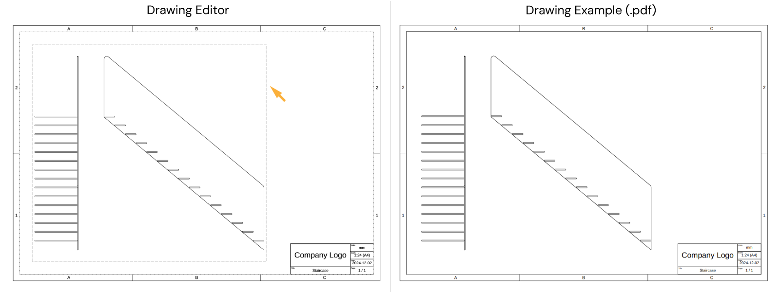
Notice that when working on the Drawing Editor, you can see the bounds of the layout when using
fitInsideas a grey-dashed rectangle (highlighted with orange arrow in picture above), that provides you immediate visual feedback of where your layout will end up, specially to check if it will overlap the drawing margins or other possible layouts.
Good job. Don't worry about the header yet, we will go through it later. As a next step let's add the dimensions to the projection layouts
B. Add Dimensions
Before you add the layouts to the contentLayout, you can add some dimensions to the layouts between the start and end
point (as SKYMATH.Vector2D). Feel free to explore all the optional arguments that exist for
layout.addDimension(startPoint, endPoint) in the SKYCAD library.
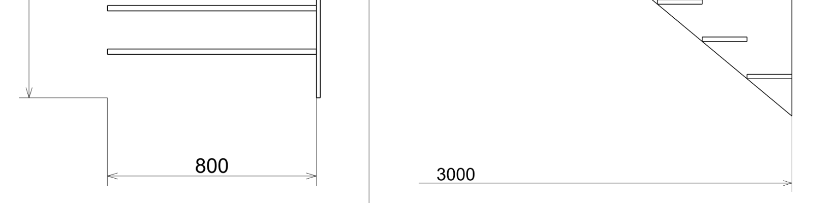
Let's add the dimensions that clearly show the width, depth and height of the staircase in the projections.
export function generateDrawing(assemblyComponent: ASSEMBLY.Component) {
  const { width, depth, height } = assemblyComponent.getProperties()
  const geometry = assemblyComponent.generateGeometry()

  // Drawing

  // Page 1

  // Content

  // --- front view
  const frontPlane = new SKYCAD.Plane(-1, 0, 0, 2000)
  const frontProjectionLayout = SKYCAD.project(geometry, frontPlane)
  frontProjectionLayout.addDimension(new SKYMATH.Vector2D(-depth, 0), new SKYMATH.Vector2D(-depth, height), {
    decimals: 0,
    offset: 300,
  })
  frontProjectionLayout.addDimension(new SKYMATH.Vector2D(-depth, 0), new SKYMATH.Vector2D(0, 0), {
    decimals: 0,
    offset: -300,
  })
  contentLayout.addLayout(frontProjectionLayout)

  // --- side view
  const sidePlane = new SKYCAD.Plane(0, 1, 0, 2000)
  const sideProjectionLayout = SKYCAD.project(geometry, sidePlane)
  sideProjectionLayout.addDimension(new SKYMATH.Vector2D(-width, height), new SKYMATH.Vector2D(0, 0), {
    decimals: 0,
    offset: -300,
    directionOfMeasurement: new SKYMATH.Vector2D(1, 0),
  })
  contentLayout.addLayout(sideProjectionLayout, {
    position: new SKYMATH.Vector2D(width + 500, 0),
  })

  // --- content in drawing

  // Header

  return drawing
}
If you want the dimensions text follow its direction automatically, you can add these lines before adding each layout to
contentLayout:frontProjectionLayout.setDefaultStyle({ defaultDimensionContinuousLines: true })
sideProjectionLayout.setDefaultStyle({ defaultDimensionContinuousLines: true })
- Save & Update (Ctrl+S) to see the dimensions.

Depending on how realistic you want your drawings to be, you should follow a standard (e.g. ISO) that determines the rules behind dimensions, view placement, etc. Knowing the different parts of a dimension (i.e. dimension line, auxiliary or extension line, arrowheads, etc) these are some general tips and rules:
- dimension lines should never cross each other or touch the projected geometry.
- auxiliary or extension lines can cross each other and can go through the projected geometry.
- dimensions should be placed so that the text can be read comfortably.
- dimensions should not be redundant or confuse the reader.
- dimensions should be placed in proper views so that they are shown clearly.
- dimensions should be thinner that the lines of the projected geometry.
C. Line Thickness
Before adding the isometric view, let's change the line thickness of the layouts, so we follow the last tip mentioned
above. You can do it by changing the argument of every layout used. However if all these are added to the same layout,
you can change its optional arguments, overwriting the settings of all the sublayouts that don't use the default ones.
So for that, let's modify the optional arguments of contentLayout:
export function generateDrawing(assemblyComponent: ASSEMBLY.Component) {
  // Properties & geometry

  // Drawing

  // Page 1

  // Content
  const contentLayout = new SKYCAD.Layout({
    defaultSketchLineThickness: 0.5,
    defaultDimensionLineThickness: 0.001,
  })

  // --- front view

  // --- side view

  // --- content in drawing

  // Header

  return drawing
}
- Save & Update (Ctrl+S) to see the dimensions thinner.
If you zoom-in in the drawing-preview downloaded as PDF, you will see the difference in line thicknesses:
And finally, let's add the isometric view on top of the header with a specific scale.
D. Isometric view
An isometric view is nothing more than another projection with a different direction. As you have noticed, projections
are always orthographic, regardless of the component perspective view. Let's say we want to have a 1 : 80 scale for it
and place it slightly above the header (which has 24 mm of height if you check its size by accessing the bounds of the
layout through layout.getBounds().getSize()):
export function generateDrawing(assemblyComponent: ASSEMBLY.Component) {
  // Properties & geometry

  // Drawing

  // Page 1

  // Content

  // --- front view

  // --- side view

  // --- content in drawing

  // Isometric view
  const isoScale = 1 / 80
  const isoProjectionLayout = new SKYCAD.Layout()
  const isoPlane = new SKYCAD.Plane(-1, 1, 1, 2000)
  const projectionLayout = SKYCAD.project(geometry, isoPlane)
  isoProjectionLayout.addLayout(projectionLayout)
  const isoProjectionLayoutSize = isoProjectionLayout.getBounds().getSize()
  isoProjectionLayout.addText(`1 : ${1 / isoScale}`, {
    position: new SKYMATH.Vector2D(-isoProjectionLayoutSize.x / 2, -750),
    align: 'center',
  })

  drawing.addContent(pageNr, isoProjectionLayout, {
    position: new SKYMATH.Vector2D(pageSize.x - 2.5 * margin, 40),
    scale: isoScale,
    textSize: 3,
  })

  // Header

  return drawing
}
Ideally you could use the argument fitInside and extract scaleLabel to add it later as text. However, for simplicity
of the tutorial see that we use a fixed scale of 1:80.
- Save & Update (Ctrl+S) to see the isometric view above the default header.

In technical drawings, the standard says that layouts that don't follow the scale of the drawing should have their scale visible. E.g. in this case we added
1 : 80below the only layout that is not scaled1 : 26as the drawing says.
Great! Now we can say we are done with the views and projections and we can move on with the header.
3. Modify Header
A header is nothing more than a SKYCAD.Table with rows and columns. Each cell is customizable, i.e custom labels, row/column span, color, etc. Here we will add a picture as a logo and add an extra column for the projection standard used and the revision number for example.
A. Add Logo
- Download any picture you want for your logo.
- Go back to the app dashboard.
- Upload your picture under Files and give it the default name, in this case we chose DYNAMAKER_LOGO_PNG.
- Still in the dashboard, create an image under Images from that file, so its name results in DYNAMAKER_LOGO.
- Go again into DrawingTemplate.
- In
edit/hide imports...(below the top tabs), make sure to importASSETS(if you don't see it, try refreshing with the spinning arrow icon and nowASSETSshould show up if you uploaded a file correctly) - In DRAWING, go the function
generateHeaderLayout()and replace thelogodefinition (you can search with Ctrl+F) with:
const logo = ASSETS.IMAGES.DYNAMAKER_LOGO
- Save & Update (Ctrl+S) to see the DynaMaker logo in the header.
The logo becomes autoscaled to fit the maximum space possible in the cell due to the logic that is added right after this row. Of course, you can change the scale and remove the logic (or even just adjust the variable created for it named
logoMaxWidth)
B. Add New Column
We will add an extra column to the table in the middle including two cells:
- one with two rows for showing the projection standard with a picture, i.e. ISO for European.
- one for the revision number, in case later manufacturing changes are approved.
Both functionalities will be added in the function generateHeaderLayout(). You can be creative in this part as long as
it's clear. E.g. you could end up having something like:
function generateHeaderLayout(
  args: {
    scale?: string
    nPages?: number
    pageNr?: number
    title?: string
  } = {},
) {
  const scale = args.scale ?? '1:1'
  const pageNr = args.pageNr ?? 1
  const nPages = args.nPages ?? 1
  const title = args.title ?? 'Staircase'

  // Table
  const defaultTextSize = 3
  const rowHeight = 2 * defaultTextSize
  const table = new SKYCAD.Table({
    defaultTextSize,
    columnWidths: [60, 30, 20],
    rowHeights: [rowHeight, rowHeight, rowHeight, rowHeight],
  })

  // First column
  table.addText('', 0, 0, { rowspan: 3 })
  table.addText(title, 3, 0, { label: 'Title' })

  // Second column
  table.addText('', 0, 1, { label: 'ISO', rowspan: 3 })
  table.addText('1', 3, 1, { label: 'Revision' })

  // Third column
  table.addText('mm', 0, 2, { label: 'Units' })
  table.addText(scale, 1, 2, { label: 'Scale' })
  table.addText(new Date().toISOString().split('T')[0]!, 2, 2, { label: 'Date' })
  table.addText(`${pageNr} / ${nPages}`, 3, 2, { label: 'Page' })

  // Logo
  const logo = ASSETS.IMAGES.DYNAMAKER_LOGO
  const logoCellPadding = 3
  const logoCellWidth = logo.width - 2 * logoCellPadding
  const logoCellHeight = 3 * rowHeight - 2 * logoCellPadding
  const logoScale = Math.min(logoCellWidth / logo.width, logoCellHeight / logo.height)
  const logoWidthScaled = logo.width * logoScale
  const logoHeightScaled = logo.height * logoScale
  table.setColumnWidth(0, logoWidthScaled + 2 * logoCellPadding)

  // Table to Layout
  const headerLayout = table.generateLayout()
  const headerSize = headerLayout.getBounds().getSize()
  headerLayout.addImage(logo, {
    position: new SKYMATH.Vector2D(
      logoCellPadding,
      headerSize.y - logoCellPadding - (logoCellHeight + logoHeightScaled) / 2,
    ),
    scale: logoScale,
  })
  // headerLayout.addImage(ASSETS.IMAGES.ISO_STANDARD, { // use your own picture
  //   position: new SKYMATH.Vector2D(63, 9), // adjust according to your picture
  //   scale: 0.032 // adjust according to your picture
  // })

  return headerLayout
}
You could also reuse the logic used for autofitting the logo into the cell as done in the template. Here we simply write the numbers needed for the position & scale, since the header size won't be dynamic for simplicity of the tutorial.
- Save & Update (Ctrl+S) to see your new header with an extra column.
See that some presets might collide with the header. In order to avoid that, you can adjust contentBounds. The
following should be enough:
const contentBounds = new SKYCAD.Bounds2D(
  new SKYMATH.Vector2D(margin, 0.12 * pageSize.y),
  new SKYMATH.Vector2D(0.65 * pageSize.x, pageSize.y - 3 * margin),
)
As for the images, you see that a cell with no text is added so that when the table is converted into a layout the image can be added to the layout with a certain position and scale.

Great. We will add another table at the top-right corner that contains the list of components intended for manufacturing, i.e. bill of materials (BOM).
4. BOM List
We will fetch the instances with their components so that we can display their name, size and quantity. This data could be created in the Assembly and then used in the drawing to create the table accordingly.
A. Components BOM
- Go back to the app dashboard.
- Go into the Assembly and go to COMPONENTS.
- Create a new function within the
class Component(e.g. likegenerateGeometry()) that creates list of objects with propertiesname,size&qty, and name it e.g.getComponentsData():
export class Component extends STUDIO.BaseComponent<CONSTANTS.Properties> {
  constructor() {
    // logic of constructor()
  }

  update() {
    // logic of update()
  }

  generateGeometry() {
    // logic of generateGeometry()
  }

  getComponentsData() {
    const { width, depth, height } = this.properties
    // Steps
    const steps = this.componentHandler.getInstances(STEP.Component)
    const stepComponent = steps[0]!.getComponent()
    const stepWidth = stepComponent.getProperty('width')
    const stepThickness = stepComponent.getProperty('height')
    const stepData = {
      name: 'Step',
      size: `${stepWidth}x${depth}x${stepThickness}`,
      qty: steps.length,
    }

    // Railing
    const railings = this.componentHandler.getInstances(RAILING.Component)
    const railingComponent = railings[0]!.getComponent()
    const railingHeight = railingComponent.getProperty('railingHeight')
    const glassThickness = 15 // should be connected to a constant from Railing instead
    const railingData = {
      name: 'Railing',
      size: `${width}x${height + railingHeight}x${glassThickness}`,
      qty: railings.length,
    }

    return {
      stepData,
      railingData,
    }
  }
}
- Save & Update and Publish your component to be able to use this function in DrawingTemplate.
Notice that in this case, all the instances share the same component (i.e. with the same properties). However, that's not usually the case. We might have steps which differ in size and therefore we should have a list with all
stepDatathat includes all types of steps with different sizes, quantities, name, etc. For simplification, we have created 1 data for each type of component.If you want to have a more robust way of creating a BOM, you can check the section BOM of this how-to example.
B. Add New Table
- Good. Now go back to the dashboard and go into DrawingTemplate.
- In DRAWING, create the function
generateBomLayout()that generates a layout from a table (same as the header) that usesgetComponentsData()from the component Assembly. Place it outsidegenerateDrawing(). E.g.:
function generateBomLayout(assemblyComponent: ASSEMBLY.Component) {
  const componentsData = assemblyComponent.getComponentsData() // Refresh the page (F5) to reload the Intellisense if this is still highlighted in red. Make sure you published Assembly.

  const table = new SKYCAD.Table({
    defaultTextSize: 3,
    columnWidths: [15, 30, 10],
  })

  let rowNr = 0

  // Title row
  table.addText('Name', rowNr, 0)
  table.addText('Size', rowNr, 1)
  table.addText('Qty', rowNr, 2)
  rowNr++

  // Railing row
  table.addText(`${componentsData.railingData.name}`, rowNr, 0)
  table.addText(`${componentsData.railingData.size}`, rowNr, 1)
  table.addText(`${componentsData.railingData.qty}`, rowNr, 2)
  rowNr++

  // Steps row
  table.addText(`${componentsData.stepData.name}`, rowNr, 0)
  table.addText(`${componentsData.stepData.size}`, rowNr, 1)
  table.addText(`${componentsData.stepData.qty}`, rowNr, 2)

  const layout = table.generateLayout()
  return layout
}
- In
generateDrawing(), add this layout as content to the drawing in the top-right corner:
export function generateDrawing(assemblyComponent: ASSEMBLY.Component) {
  // Properties & geometry

  // Drawing

  // Page 1

  // Content (front view, side view, content to drawing)

  // Isometric view

  // BOM
  const bomLayout = generateBomLayout(assemblyComponent)
  drawing.addContent(pageNr, bomLayout, { align: { vertical: 'top', horizontal: 'right' } })

  // Header

  return drawing
}

function generateHeaderLayout(args) {
  // logic of generateHeaderLayout()
}

function generateBomLayout(assemblyComponent: ASSEMBLY.Component) {
  // logic of generateBomLayout()
}
Adding content with only
alignplaces the layout so that it's automatically moved to the drawing corners, making it ideal to place tables to the drawing. Alternatively, usepositionto place the content freely within the page.
- Save & Update to see the BOM table at the top-right.

5. Drawing Format
As the last step, the drawing will change to scale 1 : 1 when it's for a DXF so that the customer has the design with
real dimensions and can measure freely without any problem. For that, we will adjust some scales with simple
if-statements in DrawingTemplate, remove the isometric view for the DXF, and adjust the page size accordingly. Also,
presets will help to see the differences right away.
- First off, let's add an argument in
generateDrawing(), e.g.fileType, adjust the scale in the header, remove the isometric view and return a new drawing (trueSizeDrawing) that has the content scaled accordingly. You can create a variableenum FILE_TYPEto assist your coding.
export enum FILE_TYPE {
  PDF = 'pdf',
  DXF = 'dxf',
}

export function generateDrawing(assemblyComponent: ASSEMBLY.Component, { fileType = FILE_TYPE.PDF } = {}) {
  // Properties & geometry

  // Drawing

  // Page 1

  // Content

  // --- front view

  // --- side view

  // --- content to drawing
  const validScales = [1]
  for (let i = 0; i < 300; i++) validScales.push(1 / i)
  const { scale, scaleLabel } = drawing.addContent(pageNr, contentLayout, {
    // get scale to rescale true-size drawing
    // rest of arguments as before
  })

  // Isometric view
  if (fileType === FILE_TYPE.PDF) {
    // logic of isometric view
  }

  // BOM

  // Header
  const headerLayout = generateHeaderLayout({
    title: 'Staircase',
    pageNr,
    nPages: drawing.getPages().length,
    scale: fileType === FILE_TYPE.PDF ? `${scaleLabel} (A4)` : `1:1`,
  })
  drawing.setHeader(pageNr, headerLayout)

  if (fileType === FILE_TYPE.PDF) {
    return drawing
  } else {
    // (fileType === FILE_TYPE.DXF)
    const page1 = drawing.getPages()[0]!
    const trueSizeLayout = page1.generateLayout()
    trueSizeLayout.scale(1 / scale)
    const trueSizeDrawing = new SKYDRAWING.Drawing()
    const trueSizePageHeight = pageSize.y / scale
    const trueSizePageWidth = pageSize.x / Scale
    trueSizeDrawing.addPage(pageNr, {
      pageHeight: trueSizePageHeight,
      pageWidth: trueSizePageWidth,
    })
    trueSizeDrawing.addContent(pageNr, trueSizeLayout)
    return trueSizeDrawing
  }
}
It's up to you how you want to use if-statements:
- in-line to save some space (suitable when only 2 alternatives):
const value = condition ? alternativeA : alternativeB

// same as:

const value = condition
  ? alternativeA
  : alternativeB
- most common way
let value = alternativeA
if (condition1) {
  value = alternativeB
} else if (condition2) {
  value = alternativeC
} else {
  value = alternativeD
}
- common way skipping
{}(suitable for very short logic)
let value = alternativeA
if (condition) value = alternativeB
else if (condition2) value = alternativeC
else value = alternativeD
- Secondly, try different presets so that they change
fileType. In PRESETS add new components in new cases as:
export const drawingPreset = new PRESET.PresetDrawing(DRAWING.generateDrawing)

// assemblyComponentA

// assemblyComponentB

const assemblyComponentC = new ASSEMBLY.Component()
assemblyComponentC.setProperties({ width: 3000, depth: 1000, height: 4500 })
drawingPreset.addCase([assemblyComponentC, { fileType: DRAWING.FILE_TYPE.PDF }], {
  label: 'PDF - W: 3000, D: 1000, H: 4500',
})

const assemblyComponentD = new ASSEMBLY.Component()
assemblyComponentD.setProperties({ width: 3000, depth: 1000, height: 4500 })
drawingPreset.addCase([assemblyComponentD, { fileType: DRAWING.FILE_TYPE.DXF }], {
  label: 'DXF - W: 3000, D: 1000, H: 4500',
})
- Save & Update to apply changes to the presets
- Switch presets in the dropdown of the top-left corner of the preview section.
In a DXF editor that allows real measurements, you will see that new manual dimensions in the drawing will have the exact real measurements, since the scale is now 1:1, matching the predefined dimensions. Naturally, when having a PDF format, the dimensions will be scaled accordingly.
Remember that the buttons 📥 PDF and 📥 DXF at the top-left corner of the Drawing Editor download the preview-drawing that is currently shown as a PDF and DXF file respectively. It has nothing to do with the variable
fileType, which is something that will be most likely used in the UI Editor (not covered in this tutorial). As always, we show the common example of use below.
Congratulations! You have created your first drawing. Having it in an app could look like this (check 📥 Export):
Do you want to have a copy of this app in your team? Let us know at support@dynamaker.com! Remember that everyone has their own way of developing and there are multiple valid ways to do things as long as anyone can understand the code!
Now that you know how to autogenerate drawings dynamically, it is time to explain one more powerful feature before we dive into the app itself, and that is the configurator. Go on to the next tutorial Configurators to learn more!