How To Use Connectors
In DynaMaker it is very easy to add components at specific points of other components. By using connectors as a bundle of position and rotation, subcomponents can be added through the component handler in a simpler way.
To explain how they work, we take a robot arm as the product example. Each part or component of the robot will contain a list of connectors. This robot will be modelled from an open-source robot arm and put in an app by following these steps:
A. Prepare Components
To make it simpler for this example, we have prepared and assembled the parts accordingly so the STL files are lighter and ready for use with connectors, but feel free to use the full model instead with all the lids and screws if you wish. A component will be created for each main part of the robot arm. Then, connectors will be added accordingly and finally, the assembly will know how to populate those connectors with the respective subcomponents. Let's go step by step:
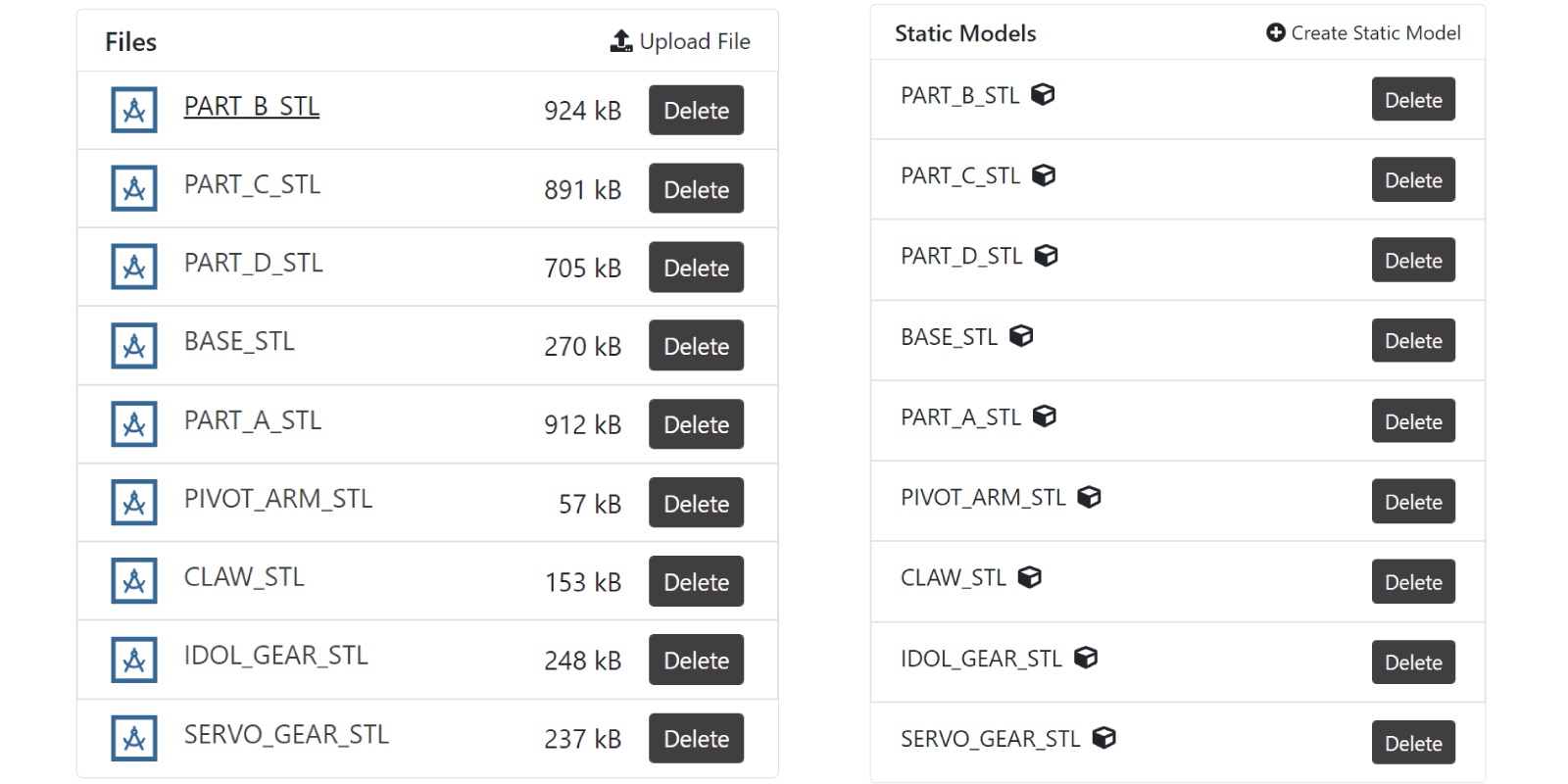
- Download all the simpler STL files together with the official manual here.
- Upload them to the DynaMaker project and create a static model for each:
- Create a component for each part together with an Assembly component. You can bundle the claw, gears and pivot arms into Tool, so the final result would look something like this:
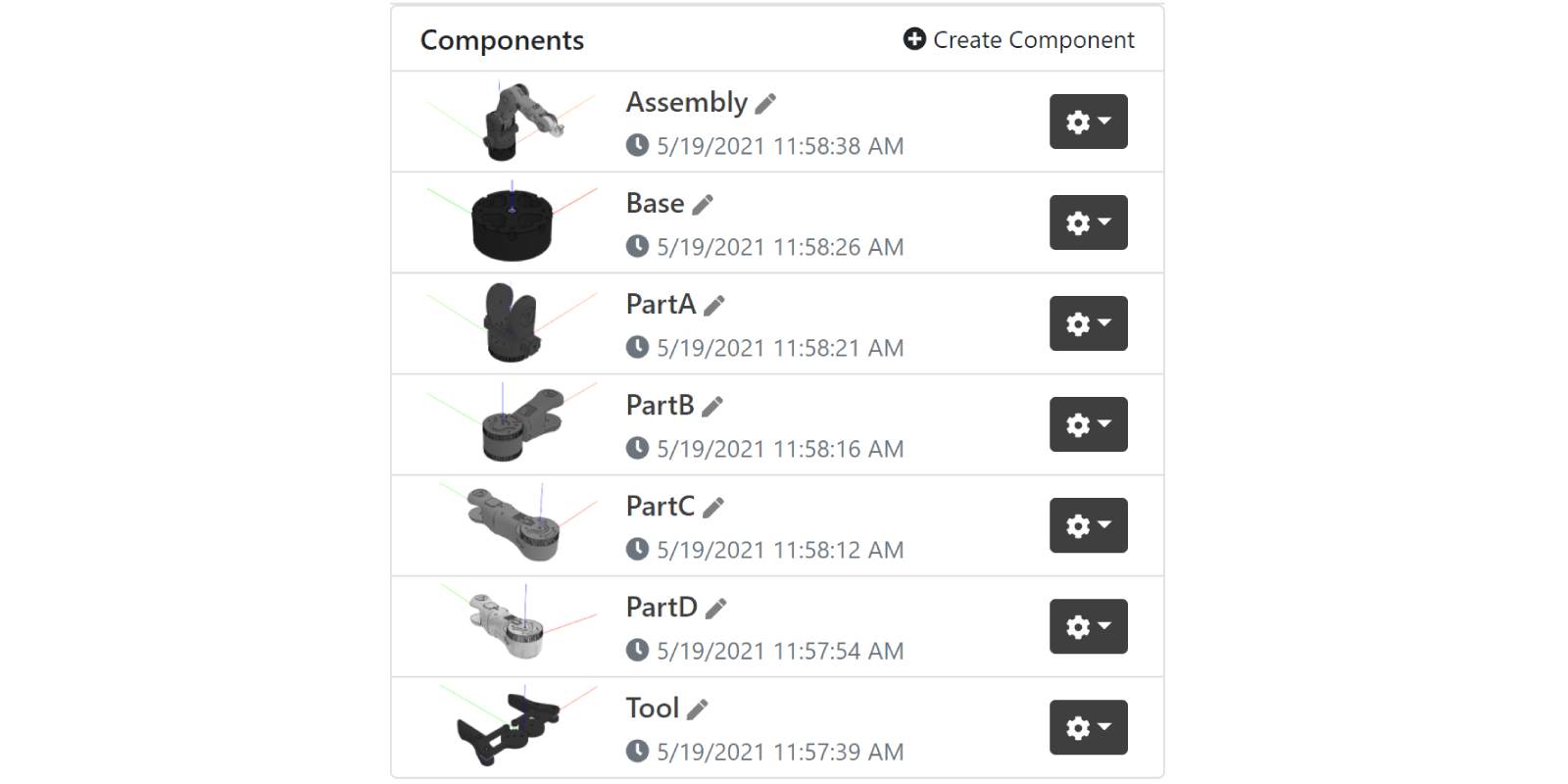
Once we have the components ready, let's add the connectors for each one of them.
B. Subcomponent Connectors
To cache the models properly, they need to be created outside generateGeometry(), then they can be added to the
geometry with the position and rotation desired.
- In GEOM3D, create the model from the static model as:
export const baseModel = ASSETS.STATIC_MODELS.BASE_STL
- In COMPONENTS, add the model to the geometry in
generateGeometry()with a color, like:
generateGeometry() {
  const geometryGroup = new SKYCAD.GeometryGroup()
  geometryGroup.addGeometry(GEOM3D.baseModel, {
    materials: [new SKYCAD.Material({ color: 0x222222 })],
  })
  return geometryGroup
}
- Add a connector for the following part (Part A in this case) within the
classin the standard functiongetConnectors(). Also, add atagso it's easier to retrieve later in the component Assembly:
getConnectors() {
  return [
    new SKYCAD.Connector3D({ position: new SKYMATH.Vector3D(0, 0, 65), tags: ['part-a'] }),
  ]
}
See that using the function
getConnectors(), which returns a list of connectors, will result in visualizing the connectors in the current Component Editor as a small blue-ish coordinate system.

Repeat these 3 steps for parts A through D (you can expand the sections below) and leave the Tool for the following section.
Show Part A logic:
// GEOM / GEOM3D
export const partAModel = ASSETS.STATIC_MODELS.PART_A_STL

// COMP / Component
getConnectors() {
  return [
    new SKYCAD.Connector3D({
      position: new SKYMATH.Vector3D(0, 0, 165),
      rotation: new SKYMATH.Vector3D(-Math.PI / 2, 0, -Math.PI / 2),
      tags: ['part-b']
    }),
  ]
}

generateGeometry() {
  const geometryGroup = new SKYCAD.GeometryGroup()

  geometryGroup.addGeometry(GEOM3D.partAModel, {
    materials: [new SKYCAD.Material({ color: 0X444444 })],
    rotation: new SKYMATH.Vector3D(0, 0, Math.PI / 2),
  })

  return geometryGroup
}
Show Part B logic:
// GEOM / GEOM3D
export const partBModel = ASSETS.STATIC_MODELS.PART_B_STL

// COMP / Component
getConnectors() {
  return [
    new SKYCAD.Connector3D({
      position: new SKYMATH.Vector3D(220, 0, 0),
      rotation: new SKYMATH.Vector3D(0, 0, -Math.PI / 2),
      tags: ['part-c']
    }),
  ]
}

generateGeometry() {
  const geometryGroup = new SKYCAD.GeometryGroup()

  geometryGroup.addGeometry(GEOM3D.partBModel, {
    materials: [new SKYCAD.Material({ color: 0X666666 })],
    rotation: new SKYMATH.Vector3D(0, 0, -Math.PI / 2)
  })

  return geometryGroup
}
Show Part C logic:
// GEOM / GEOM3D
export const partCModel = ASSETS.STATIC_MODELS.PART_C_STL

// COMP / Component
getConnectors() {
  return [
    new SKYCAD.Connector3D({
      position: new SKYMATH.Vector3D(0, 222.5, 0),
      rotation: new SKYMATH.Vector3D(Math.PI , 0, Math.PI),
      tags: ['part-d']
    }),
  ]
}

generateGeometry() {
  const geometryGroup = new SKYCAD.GeometryGroup()

  geometryGroup.addGeometry(GEOM3D.partCModel, {
    materials: [new SKYCAD.Material({ color: 0X888888 })],
    position: new SKYMATH.Vector3D(-35, 127.5, 0),
    rotation: new SKYMATH.Vector3D(0, 0, - Math.PI / 2),
  })
  return geometryGroup
}
Show Part D logic:
// GEOM / GEOM3D
export const partDModel = ASSETS.STATIC_MODELS.PART_D_STL

// COMP / Component
getConnectors() {
  return [
    new SKYCAD.Connector3D({
      position: new SKYMATH.Vector3D(0, 65, 0),
      rotation: new SKYMATH.Vector3D(0, -Math.PI / 2, 0),
      tags: ['tool']
    }),
  ]
}

generateGeometry() {
  const geometryGroup = new SKYCAD.GeometryGroup()

  geometryGroup.addGeometry(GEOM3D.partDModel, {
    materials: [new SKYCAD.Material({ color: 0XBBBBBB, opacity: 0.95 })], // some opacity will help to see how the gears move inside
  })

  return geometryGroup
}

Other values for positions and rotations of the models and connectors may be valid as well depending on how they are connected with the parameters later and their default values.
Tool logic
The tool of the robot arm consists of 4 different parts: the claws, the left and right gear that are connected to,
together with the pivot arms that strengthen the movement. We will include a property openingPercentage that tells how
much the tool is open so that the angle with which the parts are rotated will be easier to calculate. For this:
- In CONSTANTS update
Properties:
export interface Properties {
  openingPercentage: number
}
- In COMPONENTS update the component properties:
this.properties = {
  openingPercentage: 0.7,
}
- In GEOM3D create the 4 models from the static assets:
export const clawModel = ASSETS.STATIC_MODELS.CLAW_STL
export const pivotArmModel = ASSETS.STATIC_MODELS.PIVOT_ARM_STL
export const idolGearModel = ASSETS.STATIC_MODELS.IDOL_GEAR_STL
export const servoGearModel = ASSETS.STATIC_MODELS.SERVO_GEAR_STL
- In COMPONENTS within the
class, creategetAngle()that calculates the angle for the rotation of the parts, based onopeningPercentageand add the models to the geometry ingenerateGeometry()with the help ofgetConnectors()to add the claws so they don't rotate withopeningPercentage.
getAngle() {
  const { openingPercentage } = this.properties
  return (1 - openingPercentage) * 90 * Math.PI / 180
}

getConnectors() {
  const angle = this.getAngle()
  return [
    new SKYCAD.Connector3D({
      position: new SKYMATH.Vector3D(-15 - 40 * Math.cos(angle), + 40 * Math.sin(angle), 0),
      rotation: new SKYMATH.Vector3D(0, 0, 0),
      tags: ['left-claw']
    }),
    new SKYCAD.Connector3D({
      position: new SKYMATH.Vector3D(15 + 40 * Math.cos(angle), + 40 * Math.sin(angle), 0),
      rotation: new SKYMATH.Vector3D(0, Math.PI, 0),
      tags: ['right-claw']
    }),
  ]
}

generateGeometry() {
  const angle = this.getAngle()
  const geometryGroup = new SKYCAD.GeometryGroup()

  // Gears
  geometryGroup.addGeometry(GEOM3D.servoGearModel, {
    materials: [new SKYCAD.Material({ color: 0X333333 })],
    position: new SKYMATH.Vector3D(14, 0, 0),
    rotation: new SKYMATH.Vector3D(0, 0, angle),
  })
  geometryGroup.addGeometry(GEOM3D.idolGearModel, {
    materials: [new SKYCAD.Material({ color: 0X333333 })],
    position: new SKYMATH.Vector3D(-14, 0, 0),
    rotation: new SKYMATH.Vector3D(0, 0, -angle),
  })

  // Pivot arms
  geometryGroup.addGeometry(GEOM3D.pivotArmModel, {
    materials: [new SKYCAD.Material({ color: 0X333333 })],
    position: new SKYMATH.Vector3D(7, 20, -3),
    rotation: new SKYMATH.Vector3D(0, 0, angle),
  })
  geometryGroup.addGeometry(GEOM3D.pivotArmModel, {
    materials: [new SKYCAD.Material({ color: 0X333333 })],
    position: new SKYMATH.Vector3D(-7, 20, -3),
    rotation: new SKYMATH.Vector3D(0, 0, Math.PI - angle),
  })

  // Claws
  const clawsConnectors = this.getConnectors()
  const leftConnector = clawsConnectors.filter(connector => connector.hasTag('left-claw'))[0]!
  const rightConnector = clawsConnectors.filter(connector => connector.hasTag('right-claw'))[0]!

  geometryGroup.addGeometry(GEOM3D.clawModel, {
    materials: [new SKYCAD.Material({ color: 0X333333 })],
    connector: leftConnector
  })
  geometryGroup.addGeometry(GEOM3D.clawModel, {
    materials: [new SKYCAD.Material({ color: 0X333333 })],
    connector: rightConnector
  })

  return geometryGroup
}
As a result of the above, you should have a model that looks like the following for openingPercentage = 0,
openingPercentage = 0.7 and openingPercentage = 1 respectively:
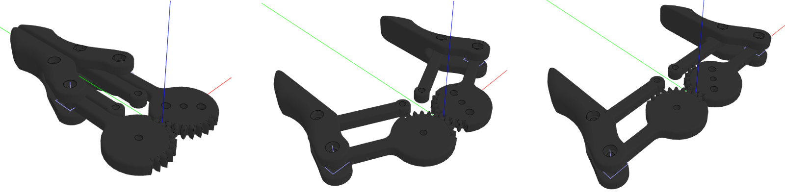
Notice that the pivot arms and the gears rotate with the angle, but not the claws since they are placed in the connectors with the tags
'left-claw'and'right-claw'.
Great! Now that we have all the components, it's time to assemble them. To add the subcomponents, we will follow a similar process as we did in the Tool component, i.e. taking the connectors of each part to add its following.
C. Assembly
Let's start with the properties. We will add a property with the rotation for each part and an extra one to connect with
the mentioned openingPercentage tool property. Then, we will update the parameters, so we get the right configurator
in the app. And finally, add the components as subcomponents to the assembly, so that the geometry is generated from all
of them.
Properties
- In CONSTANTS update
Properties:
export interface Properties {
  partARotation: number
  partBRotation: number
  partCRotation: number
  partDRotation: number
  openingPercentage: number
}
- In COMPONENTS update the component properties and call
update()for later within theconstructor:
 constructor() {
  super()

  this.properties = {
    partARotation: 270 * Math.PI / 180,
    partBRotation: 30 * Math.PI / 180,
    partCRotation: 75 * Math.PI / 180,
    partDRotation: 0 * Math.PI / 180,
    openingPercentage: 1,
  }

  this.update() // this will handle the logic for adding subcomponents later
}
Parameters
Update the configurator so that it has 4 parameters (1 for each part rotation) and a 5th for the opening percentage of the gripper tool.
export function generateConfigurator(component: COMPONENT.Component): SKYPARAM.Configurator {
  const partARotationParameter = SKYPARAM.generateSlider(PARAMETER.PART_A_ROTATION, 'Part A rotation', {
    defaultValue: Math.round((component.getProperty('partARotation') * 180) / Math.PI),
    maxValue: 359,
    minValue: 0,
    stepSize: 1,
    unit: '°',
  })
  const partBRotationParameter = SKYPARAM.generateSlider(PARAMETER.PART_B_ROTATION, 'Part B rotation', {
    defaultValue: Math.round((component.getProperty('partBRotation') * 180) / Math.PI),
    maxValue: 120,
    minValue: -120,
    stepSize: 1,
    unit: '°',
  })
  const partCRotationParameter = SKYPARAM.generateSlider(PARAMETER.PART_C_ROTATION, 'Part C rotation', {
    defaultValue: Math.round((component.getProperty('partCRotation') * 180) / Math.PI),
    maxValue: 120,
    minValue: -120,
    stepSize: 1,
    unit: '°',
  })
  const partDRotationParameter = SKYPARAM.generateSlider(PARAMETER.PART_D_ROTATION, 'Part D rotation', {
    defaultValue: Math.round((component.getProperty('partDRotation') * 180) / Math.PI),
    maxValue: 120,
    minValue: -120,
    stepSize: 1,
    unit: '°',
  })
  const openingPercentageParameter = SKYPARAM.generateSlider(PARAMETER.OPENING_PERCENTAGE, 'Opening Percentage', {
    defaultValue: Math.round(component.getProperty('openingPercentage') * 100),
    maxValue: 100,
    minValue: 0,
    stepSize: 1,
    unit: '%',
  })

  const configurableParameters = [
    partARotationParameter,
    partBRotationParameter,
    partCRotationParameter,
    partDRotationParameter,
    openingPercentageParameter,
  ]

  const configurator = new SKYPARAM.Configurator(configurableParameters)

  configurator.addUpdateCallback((validUserInput, values) => {
    if (validUserInput) {
      component.setProperties({
        partARotation: (values[PARAMETER.PART_A_ROTATION] * Math.PI) / 180,
        partBRotation: (values[PARAMETER.PART_B_ROTATION] * Math.PI) / 180,
        partCRotation: (values[PARAMETER.PART_C_ROTATION] * Math.PI) / 180,
        partDRotation: (values[PARAMETER.PART_D_ROTATION] * Math.PI) / 180,
        openingPercentage: values[PARAMETER.OPENING_PERCENTAGE] / 100,
      })
    }
  })

  return configurator
}
Instead of having fixed max/min values, you can try to add rules to make sure the parts don't collide with each other at all possible positions. Remember also that the values presented in the parameter can differ from the actual value stored in the component. For example, the angles are presented in degrees, while in the component radians are used to be consistent.
Add Subcomponents
Use the function update() as always to clear, create and add subcomponents into the component handler. Also, use the
connectors from the component to add the following part. Don't forget to connect the Assembly properties with the
subcomponents.
update() {
  const { partARotation, partBRotation, partCRotation, partDRotation, openingPercentage } = this.properties
  this.componentHandler.clearAll()

  // Base
  const baseComponent = new BASE.Component()
  this.componentHandler.add(baseComponent)
  const baseConnectors = this.componentHandler.getConnectors(BASE.Component)

  // Part A
  const partAConnectors = baseConnectors.filter(connector => connector.hasTag('part-a'))
  const partAComponent = new PARTA.Component()
  partAConnectors.forEach(connector => {
    this.componentHandler.add(partAComponent, { connector, rotation: new SKYMATH.Vector3D(0, 0, partARotation) })
  })

  // Part B
  const partBConnectors = this.componentHandler.getConnectors(PARTA.Component).filter(connector => connector.hasTag('part-b'))
  const partBComponent = new PARTB.Component()
  partBConnectors.forEach(connector => {
    this.componentHandler.add(partBComponent, { connector, rotation: new SKYMATH.Vector3D(0, 0, partBRotation) })
  })

  // Part C
  const partCConnectors = this.componentHandler.getConnectors(PARTB.Component).filter(connector => connector.hasTag('part-c'))
  const partCComponent = new PARTC.Component()
  partCConnectors.forEach(connector => {
    this.componentHandler.add(partCComponent, { connector, rotation: new SKYMATH.Vector3D(0, 0, partCRotation) })
  })

  // Part D
  const partDConnectors = this.componentHandler.getConnectors(PARTC.Component).filter(connector => connector.hasTag('part-d'))
  const partDComponent = new PARTD.Component()
  partDConnectors.forEach(connector => {
    this.componentHandler.add(partDComponent, { connector, rotation: new SKYMATH.Vector3D(0, 0, partDRotation) })
  })

  // Tool
  const toolConnectors = this.componentHandler.getConnectors(PARTD.Component).filter(connector => connector.hasTag('tool'))
  const toolComponent = new TOOL.Component()
  toolComponent.setProperties({ openingPercentage })
  toolConnectors.forEach(connector => {
    this.componentHandler.add(toolComponent, { connector })
  })
}
Notice that when adding a component via the
componentHandler, you can use aconnectorto do so since it has the position and rotation included. See that the argumentspositionandrotationare automatically switched to be meant for local coordinates whileconnectoris meant for global coordinates. If the argumentconnectoris not used, thenpositionandrotationwill remain to be in global coordinates as always.
Geometry
Since all the subcomponents are added correctly to the component handler, you can simply generate the geometry through it:
generateGeometry() {
  return this.componentHandler.generateAllGeometry()
}
Nice assembly! You can also visualize all the connectors in the Component Editor of the Assembly. For that, you need to ask the instance for its connectors since we want to visualize them in global coordinate systems.
/**
 * Used exclusively for visualization in this Component Editor
 */
getConnectors() {
  const connectors: SKYCAD.Connector3D[] = [] // type added to prevent other items different from SKYCAD.Connector3D to be added to connectors
  // Base
  const baseInstances = this.componentHandler.getInstances(BASE.Component)
  baseInstances.forEach(instance => { connectors.push(...instance.getConnectors()) })

  // Part A
  const partAInstances = this.componentHandler.getInstances(PARTA.Component)
  partAInstances.forEach(instance => { connectors.push(...instance.getConnectors()) })

  // Part B
  const partBInstances = this.componentHandler.getInstances(PARTB.Component)
  partBInstances.forEach(instance => { connectors.push(...instance.getConnectors()) })

  // Part C
  const partCInstances = this.componentHandler.getInstances(PARTC.Component)
  partCInstances.forEach(instance => { connectors.push(...instance.getConnectors()) })

  // Part D
  const partDInstances = this.componentHandler.getInstances(PARTD.Component)
  partDInstances.forEach(instance => { connectors.push(...instance.getConnectors()) })

  // Tool
  const toolInstances = this.componentHandler.getInstances(TOOL.Component)
  toolInstances.forEach(instance => { connectors.push(...instance.getConnectors()) })

  return connectors
}
Remember that
getConnectors()is a standard function in DynaMaker and needs to be called exactly that to be able to "send" the connectors to the canvas as the small blue-ish coordinate systems.
If we put this in an app, it could look like this:
Interested in removing the model edges as shown in the app? You can easily disable them in your app, in CONTROLLER, under
productConfigurationFactory(). Simply setshowEdges: false.
When updating a model with a slider instantly, as shown in the app, model flickering may appear if the models are not cached properly. In this how-to example, we have done so by creating the static models outside the function that uses it, in the same way as done in the tutorial Custom UI. You can read more about model flickering in this FAQ.
For those who love robotics, we have also created the same robot arm with inverse kinematics (instead of forward
kinematics as shown in the previous app) so that it's the robot tool that drives the position and rotation of the rest
of the parts. We have this application as an open template and you are welcome to send a request to
support@dynamaker.com if you would like a copy of it to fiddle with! Extra visual info is added to the app, like visible
metrics with the current torque and an arrow where the load is located that changes in color depending on the momentum.
Also, notice how the max value of Tool radius changes according to Tool height so that the tool always is within
range.