How To Optimize Assets
In DynaMaker it is possible to use assets that are already created in other software or in DynaMaker itself. However they can negatively affect the app performance if not optimized correctly. This guide includes some tips that can be done in DynaMaker but most of them heavily rely on the softwares that create the static asset.
In this guide, we will cover
The optimization of 2D and 3D assets is based on two thoughts:
- DynaMaker always shows a product representation, never the 100% accurate model.
- Consider the customer's computer specs and loading times for drawings and 3D models.
2D Files
From DXF files static sketches can be created and are treated as sketches, i.e. SKYCAD.Sketch. Good to know about:
File Size
Static sketches from DXF files are typically easy to handle due to their small size (usually under 100 kB). More elements, like lines or curves, increase the file size. For 3D extrusions, just the contour should be needed, which keeps the size low. However, high-detail DXF files for purposes like 2D PDF drawings can be larger and could take longer to load. To avoid long loading times, it's best to ensure the DXF file is "clean" before uploading it to DynaMaker.
Closed contours
A common issue with extrusions is that your 2D file might not be closed or have more lines than needed, which can impact
app performance by hiding extra lines. In a simple 3D extrusion (model.addExtrude()), if the sketch isn't closed, the
CAD algorithm can't merge faces or create vertices, leading to unexpected results.
In DynaMaker, you can easily ensure sketches are closed by using sketch.lineToId(0) or sketch.curveToId(0) to
connect to the starting point. If the file comes from other software, try to:
- Fix the original: If possible, fix the DXF in the software it was created (e.g. remove double lines or layers). In certain softwares, be aware of that export issues are common.
- Create in DynaMaker: If the DXF is simple, recreate it in DynaMaker to have full control of your sketch and avoid headaches. Remember to use the Drawing Editor to create a DXF if needed.
- Manual fix: Merge open ends or remove noise if needed. Debugging or diagnosis can help, but always try to fix the issue upstream to avoid doing magic fixes in DynaMaker. More tips are available here.
Edges Count
DXF files might contain a huge amount of lines. In 3D extrusions/cuts, these are translated into faces and therefore the
algorithm use for generating the 3D model (e.g. model.addExtrude()) is forced to go through all those edges and
generate a face for each, adding time to the generation time. Therefore, removing edges beforehand could be a
life-saver.
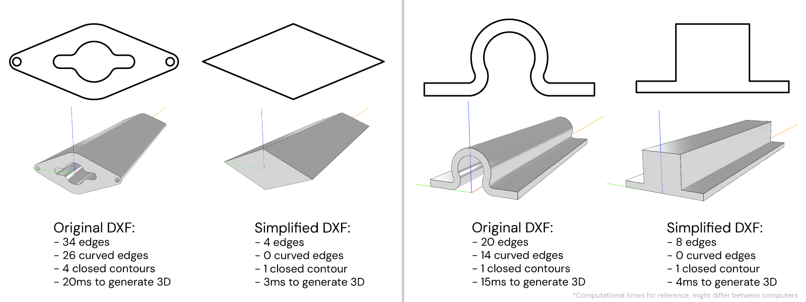
Are details relevant? Will the user notice the difference? Will this be hidden by other parts? Do I want the user to see all details? These are some questions that help you understand the simplification process of your DXF files. Removing the hollow parts of a beam profile or converting a complex side with lots of details into a single straight edge are some easy fixes to apply to your DXF files.
Curved Edges
Curved edges are a bit of a nemesis for 3D algorithms, since they are nothing more than a set of straight faces with a special treatment. Because of this, you can imagine that 3D models take a lot of time to generate when their sketches contain curves or simple holes. Reducing their number to the bare minimum or replacing them entirely with a straight edge could have a huge positive impact on performance.
Below we show 2 typical examples with holes and curved edges. See that sometimes you need to think out-of-the-box: e.g. the ◇-profile could have just the contour, since the interior is not really visible; and the Ω-profile can be converted into a upside-down T-profile because we are not interested in the gap at the bottom but only the top "bumb". In both cases however, the curved edges are completely removed, skipping completely rounded corners reducing significantly the computational time.
3D Files
From 3D files static models can be created and are treated as mesh models, i.e. SKYCAD.MeshModel. Good to know:
- CAD vs 3D-art
- File size
- Texture over 3D
- Ambient occlusion
- HDRI
- Faking shadows & lighting
- Back-face culling
These tips are explained for models in GLB format since they usually perform better than STL, and tend to be more complex (e.g. they can include textures) giving more flexibility without compromising the app performance.
CAD vs 3D-art
First-off it's crucial to understand the difference between CAD and 3D-art modelling. CAD is predominantly used for engineering and architectural purposes, focusing on technical and functional aspects of design. In contrast, 3D-art modeling often refers to creating graphics and animations in gaming, film, and virtual reality. While the first seeks accuracy and other functionalities (e.g. FEM, etc), the latter focuses heavily on pure visualization and optimization so that any computer/console can load the asset without any problem.
In DynaMaker, as a cloud-based software, 3D asset optimization is key and 3D-art modelling might make the difference to achieve a fast yet good-looking app. In the following tips, Blender will be used for reference due to being open-source and having more custom addons every day, although any other 3D-art software (Houdini for visual effects, ZBrush for 3D sculpting, etc) could be used for better results of course.
It's also good to know that 3D-art is a whole new world compared to CAD, meaning that the way of thinking is different from CAD and thus its learning curve quite steep. There are many ways of optimizing your assets and doing it properly depends entirely on skill and what's available in the software. However in the following tips we try to keep it simple.
File Size
One of the most crucial aspects regarding static models is the size of the file. The more elements a GLB contain (textures, number of surfaces, other metadata, etc), the bigger the file size. A typical case is that you start from a CAD format file (e.g. STEP) of a screw, that apparently might have a low size (767 kB as seen in picture below). However when converted to a meshed model (GLB format) a resolution must be chosen, making a huge difference in the number of polygons and therefore size as you see below.
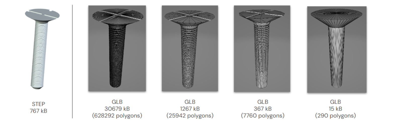
However, the lower the resolution the worse quality and details the final 3D model will have. Thus sometimes is a trade-off. You need to decide how much detail you are willing to sacrifice for the sake of having a low-size asset, i.e. fast app. Sometimes you need to think out-of-the-box and make certain decisions in the design. As you see at the very-right of the example above, the head of the screw is simplified to a cone, making the file size 4% of the one with the worst resolution (2nd to the right in picture). You could even simplify this more by removing the bottom screwed part if in the end a screw will be inside a hole, and therefore this part will be hidden.
Basically:
- decrease resolution of the output GLB from a possible STEP.
- remove parts that will not visible or the user doesn't need to know about.
- redesign model in unrealistic ways when resolution can't go lower.
Texture over 3D
Another way that makes a 3D model significantly better looking (apart from a possible huge decrease in file size) is replacing a complex 3D surface with lots of details with a texture. In the example below we show 4 examples of a wall built in DynaMaker as a rectangular extrusion with: wooden planks, metal pattern and 2 grid-types. See that instead of doing every single plank, metal bumb, wire or hole, a texture is used instead. See that a normal map (purple-ish picture) makes the lighting react differently throughout the surface.
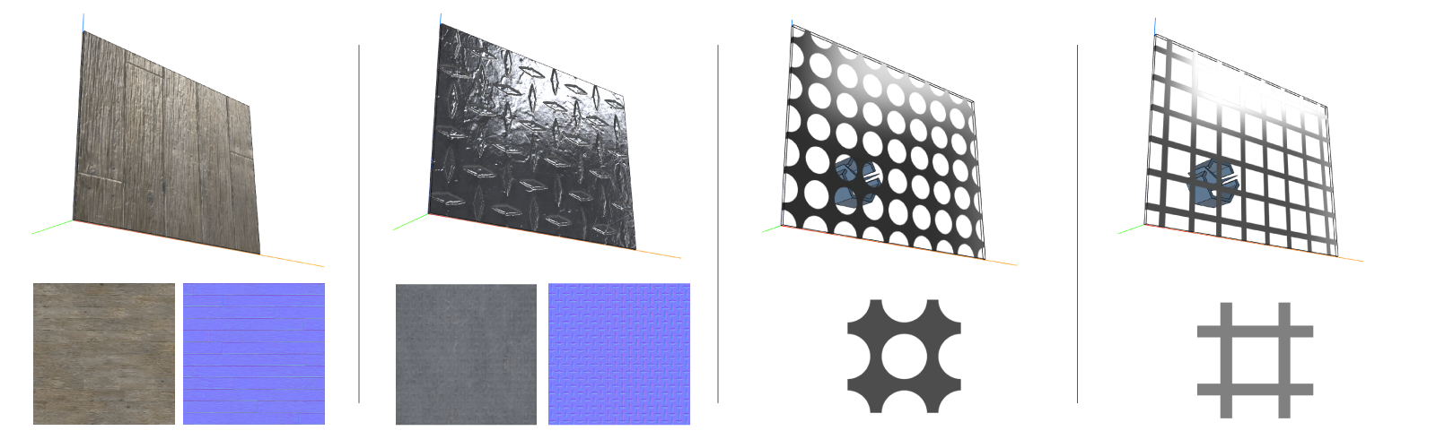
Read more about how to use textures here
But sometimes you have 3D assets with very complex surfaces, which would take forever to do in a CAD software. This is where a good GLB file plays a huge role, since it comes with built-in textures (see examples below), and therefore where a 3D-artist (and not a CAD engineer) shines.
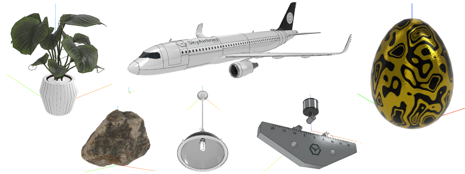
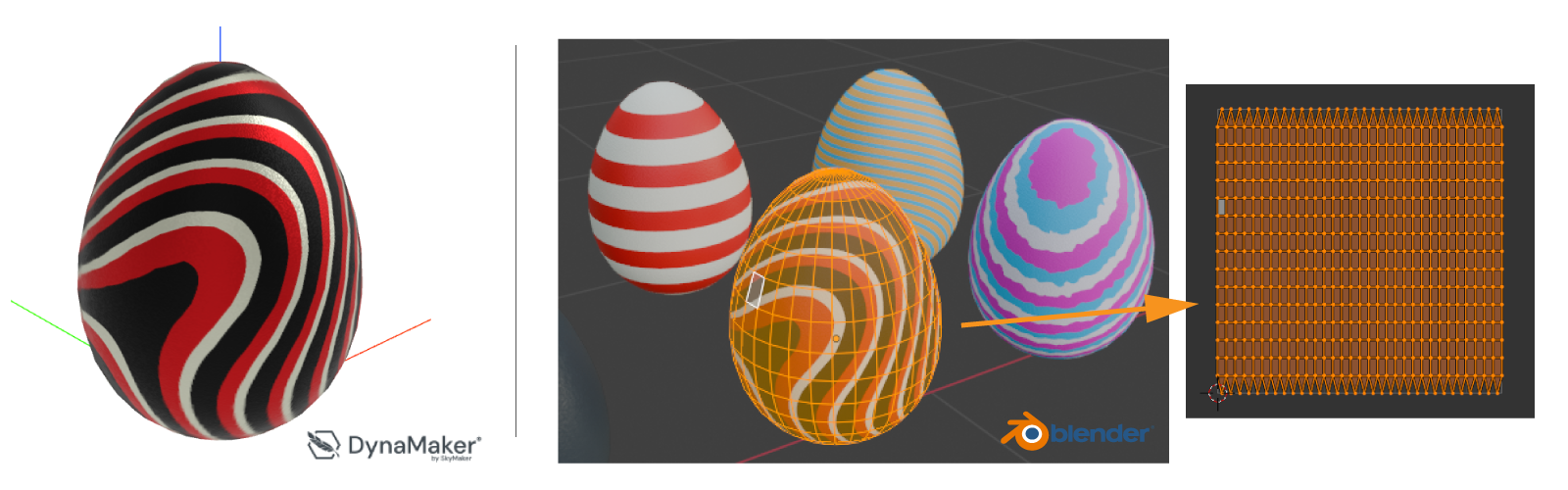
However they come with a big "but", and it's that the texture needs to be applied for every single polygon of the original GLB model mesh. If we check the egg model in Blender, we see that there are a few polygons in it (512 faces to be precised) and each one of them has part of a texture. But before adding the texture to a model as if we are painting with a brush, the process of projecting the 3D model's surface into a 2D image for image texturing, or UV mapping, of the 3D model has to be done properly.
How the texture is "distributed" or the UV mapping is incredibly dependent on the original model's mesh. In the example below with the egg, the model was created originally in Blender with the intention of adding a texture made also through Blender. If we do the UV unwrapping (i.e. mesh unfolding in 2D, see very right of the picture) the mesh is perfectly unfolded since the model was done from a sphere that has been stretched evenly in both directions.
You will see that there are lots of free available GLB models on the internet that might look exceptionally good on the outside, but when you check their UV mapping is atrocious. Therefore if you want to change/apply some textures in models you didn't create, you will realize that it's incredible difficult and it requires manual fixes (meaning changing every node/vertex/edge individually) and you will see problems right away: applied texture gets split into 2 for no reason because the egg wasn't done from a sphere, the texture at the top of the egg gets distorted becase of not being properly scaled, etc.
So assuming you start with a good model (i.e. with good UV mapping), there are 2 main ways to apply a custom texture to a 3D model:
-
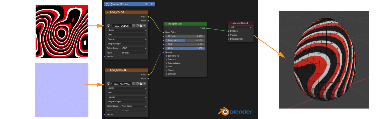
Option A: (easy) when you have the texture images already, i.e. color and normal maps (see open-source ones from ambientCG) you can add them directly to the material through the Shader Editor (in Blender), with a possible post-rescaling, which should be easy to do as long as the UV mapping (and thus the model) is correctly done.
-
Option B: (complex) build custom texture + prebake. In Blender you can create your own textures from scratch, although there are other (and better) solutions for that (see Substance Painter). But once you have your model with some custom-texturing it's not enough by just exporting said 3D model to GLB, since you will see that the custom textures will be lost in the export process. On the internet you will find that the majority of the open-source models that come in blender format (.blend), they have custom texturing and prebaking is needed.
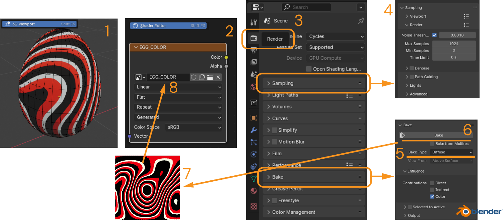
This prebaking is the equivalent of taking a "screenshot" of your model with custom-texturing, so that you can go with option A afterwards. To "convert" the custom-texturing into a texture (as image format .jpg) or bake in Blender you need (see also picture below):
- Have your model open in the 3D viewport
- Create a "Image texture" in the Shader Editor, and create a new image and name it e.g. EGG_COLOR, make sure to have
Color Space = sRGBfor color maps, andColor Space = Non-colorfor normal maps, and leave this block selected (edge should become white). - Open the Render tab at the right, here you will find tons of features around rendering, but we will focus on 2.
- In Sampling, calibrate the noise that you want to have in your texture by adjusting time limit, thresholds and such. This step might need lots of try-and-error loops, so see how results are affected by this parameter.
- In Bake, make sure
Base Type = Diffusefor color maps withColoras the onlyContribution(sinceDirectandIndirectwill include the possible direct and indirect lighting of the scene), andBase Type = Normalfor normal maps. - Bake the texture (a good graphic card should take a few seconds to finish), and if you leave the block "Image texture" selected, the resulting image (7) will be saved there (8) with the name you gave.
Then replace the custom-texturing blocks with this Image-texture block and do it as in option A. The resulting texture might not be what you want and it depends heavily on the software, although Blender does a good job most of the times, for specific examples it could be a nightmare to adjust and get the result you want.
In the example-app below, see that the same egg model is used, but with different textures. In DynaMaker textures are not really changing but the static model. In Egg 3, for each variant there's a GLB model, so keep in mind the amount of work it needs in the background and faking textures in the same model.
Ambient Occlusion
Ambient occlusion is a shading and rendering technique used to calculate how exposed each point in a scene is to ambient lighting, i.e. when enabled shadows between objects appear based on their distance with each other. Depending on the context, there are several variants of occlusion (SSAP, SSDO, RTAO, etc). Enabling this technique takes quite a lot of computational time, and you can imagine that it will be even more demanding for cloud-based solutions. Because of this, ambient occlusion in DynaMaker is disabled completely. See difference with disabled ambient occlusion (left in picture below, as it is in DynaMaker) and enabled ambient occlusion (right in picture).

However the best way to fake ambient occlusion (and this is how it's usually done in the videogame- and VR-industry due
to optimization) is by adding shadows to the textures and bake them including said shadows. To do that simply bake the
textures including the lighting of the scene. When baking in Blender make sure to have all Contributions checked to
include the lighting effect in the color map (Bake type = Diffuse), and therefore fake the ambient occlusion.
HDRI
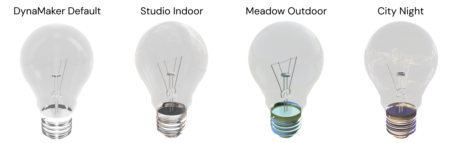
Another factor that provides more realism and immersion are the reflections. In DynaMaker there's a default environment map or HDRI, which barely affects the true colors display on screen, since it has a white-ish background with some simple 3D objects. On the Internet, there are lots of HDRIs available to download and use from open-source websites (see e.g. PolyHaven), which if used in your DynaMaker apps, the lighting might make a more suitable effect since each HDRI comes with their own light sources. In the examples below with a lightbulb, see how the HDRI Studio Indoor adds some neat lighting at the top since the HDRI includes some ceiling lamps, while the HDRI City Night drastically changes the true colors of the metallic bottom cap.
Read more about how to use HDRIs in DynaMaker here.
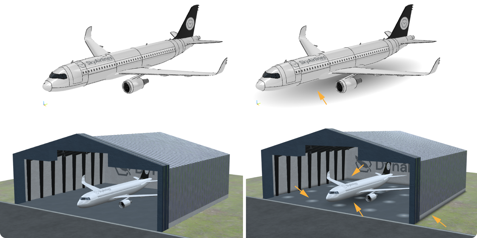
Faking Shadows & Lighting
In DynaMaker there are two scenes: room with multiple lightsources and no shadow casting, suitable for single
products; and outdoor with one sincle lightsource and shadow casting, suitable for products with some environment.
However enabling shadow casting takes quite a lot of computaton time. You will notice in apps with lots of models, that
the outdoor scene performs way worse than room, and sometimes you might wonder if more shadows can be added somehow.
So a quite efficient alternative is to fake shadows in DynaMaker, apart from baking them in textures as described in the previous sections with the ambient occlusion, you can simply add images to layouts that contain semi-transparent shadows or lighting mocking the ceiling lamps effect. Notice below that adding a few things makes the visualization look more "professional".
Read more about scene options here.
Back-face Culling
Each polygon of a meshed model has two faces: front and back. These means that each polygon has two sides, where different materials/textures can be applied to. However, rendering both sides takes literally twice the time and that happens when back-face culling is enabled, meaning that the 2nd or back side is also rendered and displayed. See example below with back-face culling enabled (left) and disabled (right).
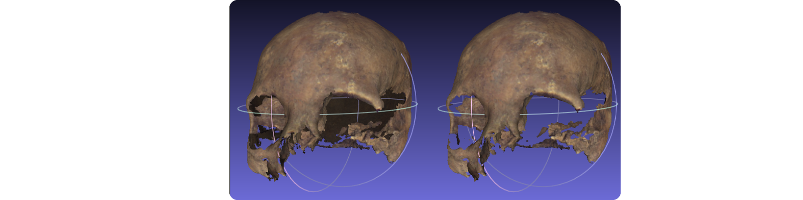
Again, as prebaking textures, disabling this technique is vastly used in the videogame- and VR-industry due to optimization and performance reasons. You might remember the nightmare of zooming into a videogame character's head and just seeing their eye globes floating in the air. This is exactly because of back-face culling disabled, i.e. the "interior" of the static models (here the head of the character) is not modelled at all.
In DynaMaker, as a cloud-solution, back-face culling is always disabled for performance reasons. But if you really want to show some back faces of your model (e.g. interior of a house that is used as environment for your outdoor product) you would need to add front faces wherever the back face is. However this is not recommended at all, since it increases the asset file size and therefore affects the app performance. This means that that you might need to think twice if you are ok letting the user see transparent faces for certain camera angles, or alternatively blocking the camera rotation between two angles (for this see Camera Handling).